

Based on the Logitech Force 3D Pro digital controller
La stazione di controllo per Rocker Tubie di cui tratta questo articolo fa parte del progetto che ho presentato in occasione del Maker Faire Europe che si è appena chiuso a Roma.
The control station's components are:
- Controller Arduino Mega 2560 R3,
- A shield USB Host Shield 2.0 di Oleg Mazurov,
- A controller Joystick Logitech Extreme 3D Pro,
- A 5A XL4015 DC-DC Step Down Adjustable Power Supply,
- A Wireless module with 2.4GHz ANTENNA, NRF24L01+ PA + LNA (range fino a 1 Km in spazi aperti),
- A power module for the NRF24L01 wireless module,
- A Full Color 10mm Bright RGB LED module.
- A 3S Lipo battery (11.1V), at least 1300mA.
- 3D printed box using 1.75mm PLA filament.
- 1 set of Male-to-Female Dupont jumper wires, 10cm.
I software da caricare sull’Arduino Mega 2560 R3 della stazione di controllo sono:
- Library for the USB Host Shield 2.0 + Logitech Force 3D Pro joystick + Arduino Mega 2560 R3.
- Sketch for running the 2.4GHz WiFi control station.
Puoi scaricarli da Rocker Tubie Fanbotica su Github.
Per i software da caricare sull’Arduino Mega 2560 R3 del rover Rocker Tubie trovi qui il link alla pagina del progetto:
The Rocker Tubie control station is a real gem!
As I explained to the many curious visitors to our Fanbotica stand at Maker Faire Europe in Rome, which just wrapped up, the Rocker Tubie control station I built is truly something special.
That's because I put a huge amount of work into it, rewriting Oleg Mazurov's original library from scratch to support digital peripherals such as the Logitech Force 3D Pro controller, which — besides being very precise — also has a third, twist (Z) axis.
In addition to digital control, my library also has other important features.
For instance, one that lets it send the 10-bit data stream coming from the Logitech peripheral as-is, without forcing the control station's microcontroller into lengthy processing.
This means that with my library, those annoying lags or delays between sending commands and the robot actually carrying them out don't occur, even at a distance of 1 km.
Wiring diagram to the Arduino Mega 2560 R3
Note: As you can see from both the diagram and the photos, the adapter module has six connection pins — CE (orange), CSN (yellow), SCK (green), MOSI (blue), MISO (purple), IRQ (gray) — all in a row along the same imaginary line, with VCC (red) and GND (brown) set apart lower down on the right.
So the connections to make are as follows:
NRF24L01+ 5V-to-3.3V adapter module –> Arduino Mega 2560 R3
CE (orange) –> PIN 48
CSN (Giallo) –> PIN 53
SCK (Verde) –> PIN 52
MOSI(Blu) –> PIN 51
MISO(Viola) –> PIN 50
IRQ (Grigio) –> Non utilizzato
VCC (red) –> 5V
GND(Marrone) –> GND
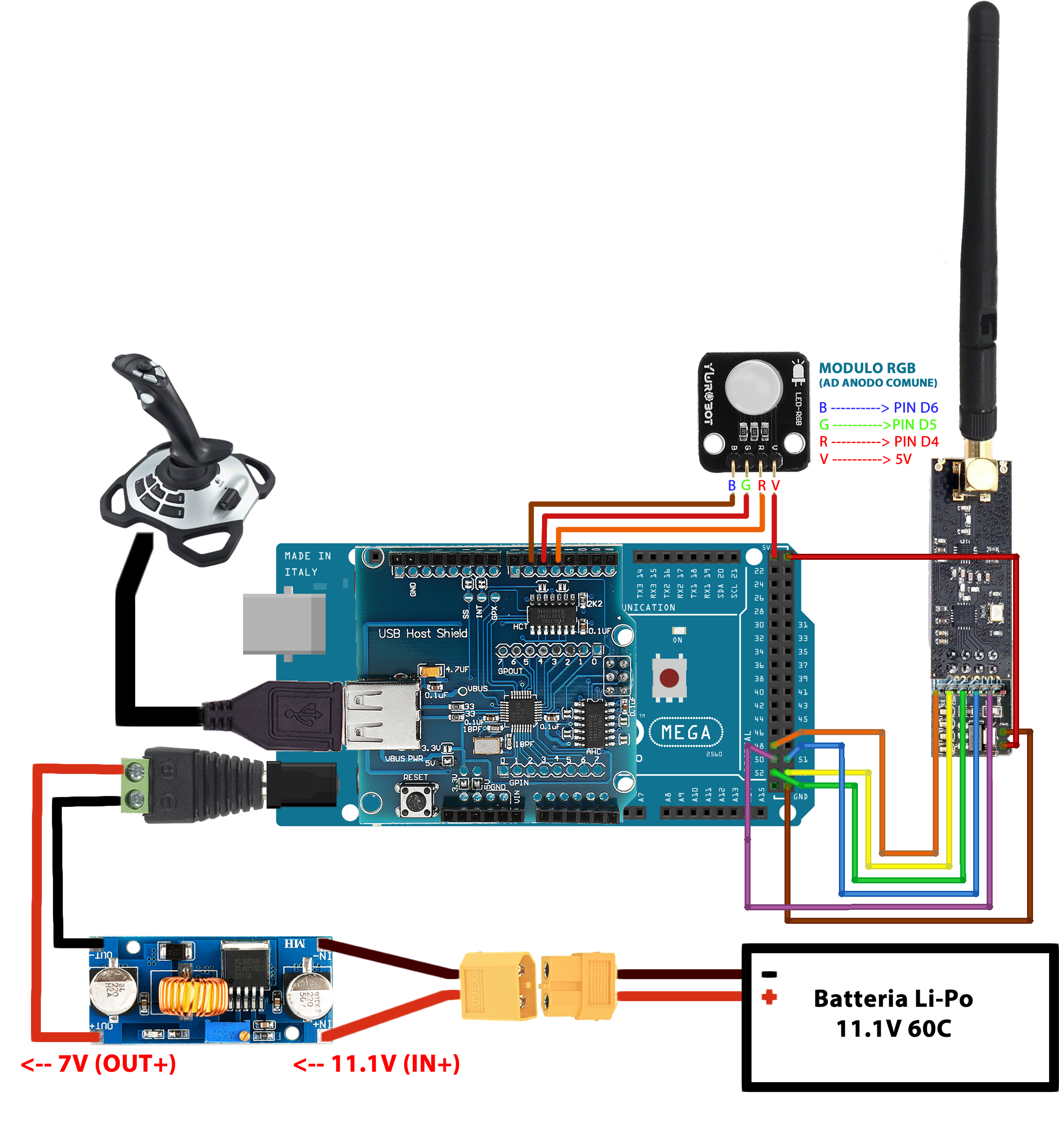 NRF24L01 Wireless Module + Arduino Mega 2560 R3_bb + RGB LED Module
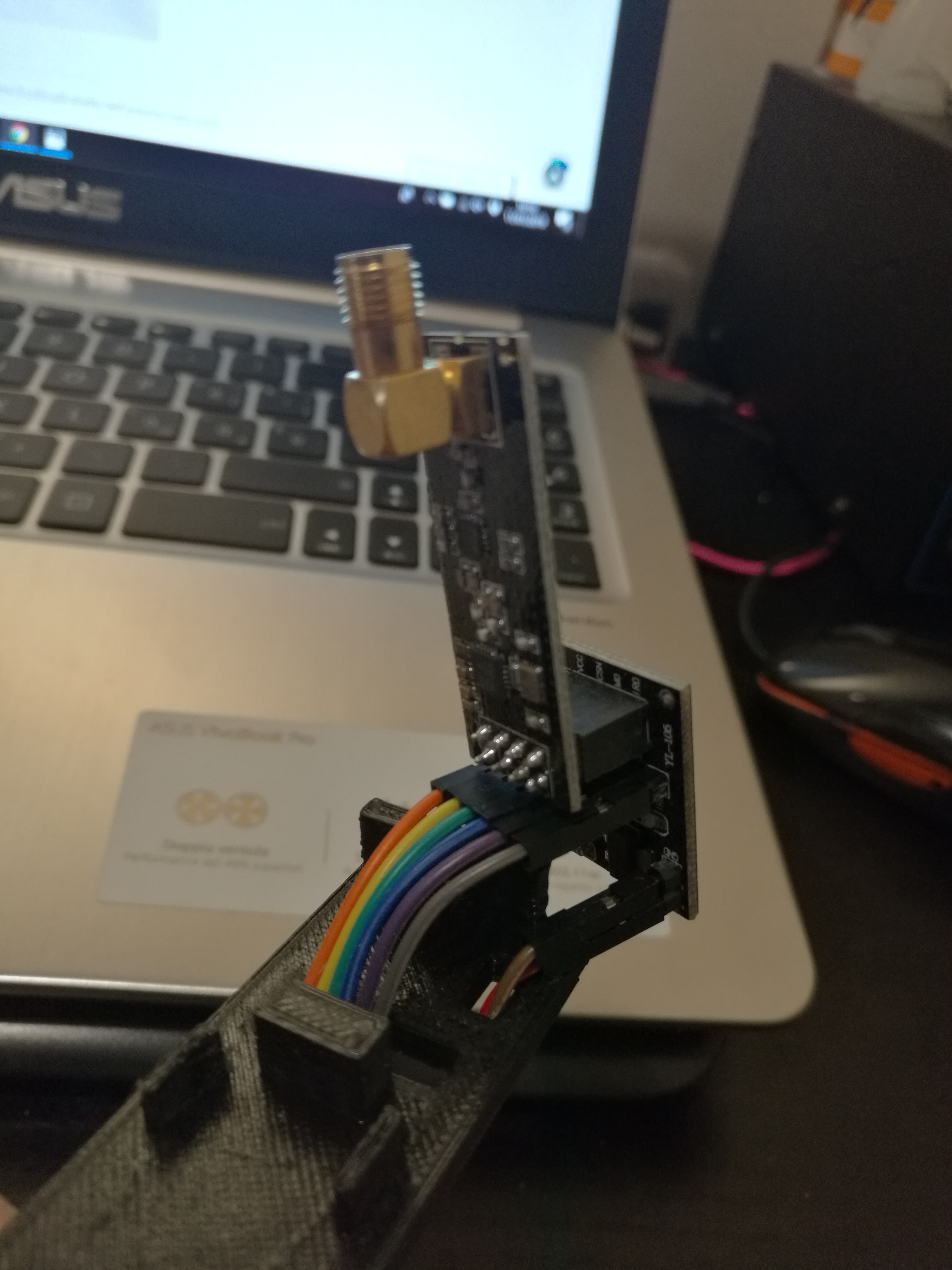 nRF24L01 power module wiring
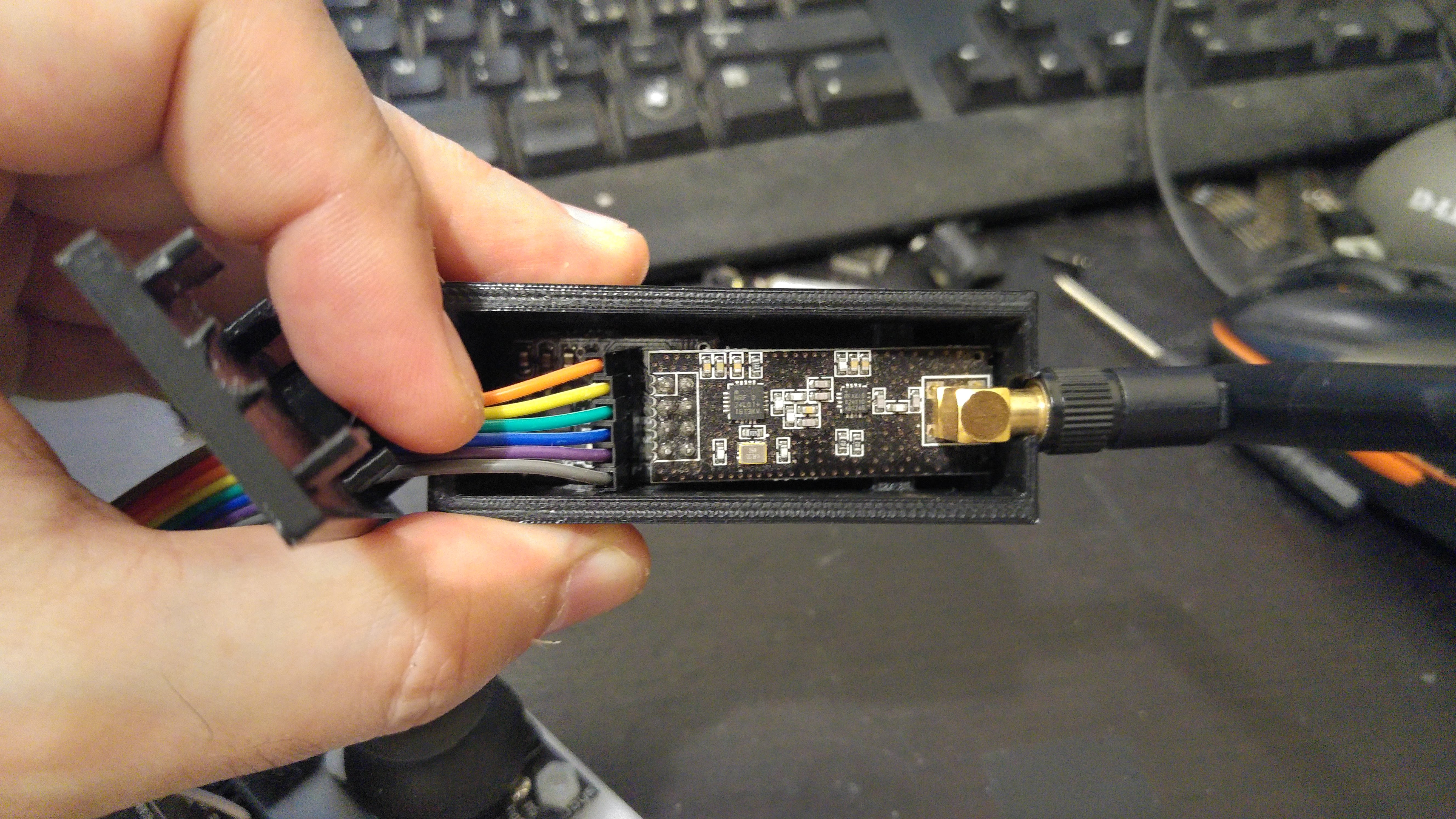 nRF24L01+ box case
 Collegamenti dei ponticelli Dupont tra nRF24L01, Mega 2560 R3 con USB Host Shield 2.0 e LED RGB.
Library for USB Host Shield 2.0 + Logitech Force 3D Pro joystick + Arduino Mega 2560 R3.
File le3dp_rptparser.
#if !defined(__HIDJOYSTICKRPTPARSER_H__)
#define __HIDJOYSTICKRPTPARSER_H__
#include <usbhid.h>
struct GamePadEventData
{
  union { //axes and hut switch
    uint32_t axes;
    struct {
      uint32_t x : 10;
      uint32_t y : 10;
      uint32_t hat : 4;
      uint32_t twist : 8;
    };
  };
  uint8_t buttons_a;
  uint8_t slider;
  uint8_t buttons_b;
};

class JoystickEvents
{
public:
	virtual void OnGamePadChanged(const GamePadEventData *evt);
};

#define RPT_GAMEPAD_LEN	sizeof(GamePadEventData)/sizeof(uint8_t)
class InitPin
{
private:
public:

  int ValX();
  int ValY();
  int ValH();
  int ValT();
  int ValS();
  int ValA();
  int ValB();
};


class JoystickReportParser : public HIDReportParser
{
	JoystickEvents		*joyEvents;

  uint8_t oldPad[RPT_GAMEPAD_LEN];

public:
	JoystickReportParser(JoystickEvents *evt);

	virtual void Parse(USBHID *hid, bool is_rpt_id, uint8_t len, uint8_t *buf);

};

#endif // __HIDJOYSTICKRPTPARSER_H__
File le3dp_rptparser.cpp
#include "le3dp_rptparser.h"
//#include <Servo.h>
#define rad2grad 57.295779513
//Servo servox, servoy, servoh, servot, servos;
int srvxval = 512;
int srvyval = 512;
int srvhval = 10;
int srvtval = 512;
int srvsval = 512;
int actaval = 0;
int actbval = 0;
double sen = 0;
float grado = 0;
JoystickReportParser::JoystickReportParser(JoystickEvents *evt) :
joyEvents(evt)
{}
void JoystickReportParser::Parse(USBHID *hid, bool is_rpt_id, uint8_t len, uint8_t *buf)
{
bool match = true;
// Checking if there are changes in report since the method was last called
for (uint8_t i=0; i<RPT_GAMEPAD_LEN; i++) {
if( buf[i] != oldPad[i] ) {
match = false;
break;
}
}
// Calling Game Pad event handler
if (!match && joyEvents) {
joyEvents->OnGamePadChanged((const GamePadEventData*)buf);
for (uint8_t i=0; i<RPT_GAMEPAD_LEN; i++) oldPad[i] = buf[i];
}
}
void JoystickEvents::OnGamePadChanged(const GamePadEventData *evt)
{
uint16_t myX = evt->x;
srvxval = myX;
// Serial.print("X: ");
// Serial.println(srvxval);
uint16_t myY = evt->y;
srvyval = myY;
// Serial.print("Y: ");
// Serial.println(srvyval);
uint16_t myH = evt->hat;
int srvH = map(myH, 0, 7, 10, 170);
srvhval = srvH;
// Serial.print("Hat: ");
// Serial.println(srvhval);
uint16_t myT = evt->twist;
srvtval = myT;
// Serial.print("Twist: ");
// Serial.println(srvtval);
// sen = sin( (srvtval/rad2grad) );
// grado = (( sen * 80 ) + 90 );
uint16_t myS = evt->slider;
srvsval = myS;
// Serial.print("Slider: ");
// Serial.println(srvsval);
uint16_t myBA = evt->buttons_a;
actaval = myBA;
// Serial.print("Buttons A: ");
// Serial.println(actaval);
uint16_t myBB = evt->buttons_b;
actbval = myBB;
// Serial.print("Buttons B: ");
// Serial.println(actbval);
/* Serial.print("X: ");
PrintHex<uint16_t>(evt->x, 0x80);
Serial.print(" Y: ");
PrintHex<uint16_t>(evt->y, 0x80);
Serial.print(" Hat Switch: ");
PrintHex<uint8_t>(evt->hat, 0x80);
Serial.print(" Twist: ");
PrintHex<uint8_t>(evt->twist, 0x80);
Serial.print(" Slider: ");
PrintHex<uint8_t>(evt->slider, 0x80);
Serial.print(" Buttons A: ");
PrintHex<uint8_t>(evt->buttons_a, 0x80);
Serial.print(" Buttons B: ");
PrintHex<uint8_t>(evt->buttons_b, 0x80);
Serial.println(""); */
}
int InitPin::ValX()
{
return(srvxval);
}
int InitPin::ValY()
{
return(srvyval);
}
int InitPin::ValH()
{
return(srvhval);
}
int InitPin::ValT()
{
return(srvtval);
}
int InitPin::ValS()
{
return(srvsval);
}
int InitPin::ValA()
{
return(actaval);
}
int InitPin::ValB()
{
return(actbval);
}
Control station sketch USBHOSTWIFI_16_MAR_2018
/* Simplified Logitech Force 3D Pro Joystick Report Parser by Francesco Onorati www.fanbotica.com*/

#include <usbhid.h>
#include <hiduniversal.h>
#include <usbhub.h>

//#include "DigitalIO.h"
#include "le3dp_rptparser.h"
#include "RF24.h"  // Download and Install (See above)
#include "printf.h" // Needed for "printDetails" Takes up some memory
/*-----( Declare Constants and Pin Numbers )-----*/
#define CE_PIN  48   // The pins to be used for CE and SN
#define CSN_PIN 53
#define redPin 4
#define greenPin 5
#define bluePin 6
#define COMMON_ANODE //uncomment this line if using a Common Anode LED

// Satisfy the IDE, which needs to see the include statment in the ino too.
#ifdef dobogusinclude
#include <spi4teensy3.h>
#include <SPI.h>
#endif

USB                                             Usb;
USBHub                                          Hub(&Usb);
HIDUniversal                                    Hid(&Usb);
JoystickEvents                                  JoyEvents;
JoystickReportParser                            Joy(&JoyEvents);
InitPin                                    inpx;
InitPin                                    inpy;
InitPin                                    inph;
InitPin                                    inpt;
InitPin                                    inps;
InitPin                                    inpa;
InitPin                                    inpb;

//int servoX;

/*-----( Declare objects )-----*/
/* Hardware configuration: Set up nRF24L01 radio on SPI bus plus (usually) pins 7 & 8 (Can be changed) */
RF24 radio(CE_PIN, CSN_PIN);

/*-----( Declare Variables )-----*/
byte addresses[][6] = {"1Node", "2Node"}; // These will be the names of the "Pipes"

unsigned long timeNow;  // Used to grab the current time, calculate delays
unsigned long started_waiting_at;
boolean timeout;       // Timeout? True or False

// Allows testing of radios and code without Joystick hardware. Set 'true' when joystick connected
//boolean hasHardware = false;
boolean hasHardware = true;

/**
  Create a data structure for transmitting and receiving data
  This allows many variables to be easily sent and received in a single transmission
  See http://www.cplusplus.com/doc/tutorial/structures/
*/
struct dataStruct {
  unsigned long _micros;  // to save response times
  int Xposition;          // The Joystick position values
  int Yposition;
  int Hposition;          // The Joystick position values
  int Tposition;
  int Sposition;          // The Joystick position values
  int Abutton;
  int Bbutton;          // The Joystick push-down switch
} myData;                 // This can be accessed in the form:  myData.Xposition  etc.


void setup()
{
  pinMode(redPin, OUTPUT);
  pinMode(greenPin, OUTPUT);
  pinMode(bluePin, OUTPUT);

  Serial.begin( 115200 );
#if !defined(__MIPSEL__)
  while (!Serial); // Wait for serial port to connect - used on Leonardo, Teensy and other boards with built-in USB CDC serial connection
#endif
  Serial.println("Start");

  if (Usb.Init() == -1)
      Serial.println("OSC did not start.");

  delay( 5 );

  if (!Hid.SetReportParser(0, &Joy))
      ErrorMessage<uint8_t>(PSTR("SetReportParser"), 1  );
  // NOTE: The "F" in the print statements means "unchangable data; save in Flash Memory to conserve SRAM"
  Serial.println(F("Fanbotica.com Example: Send joystick data by nRF24L01 radio to Rocker Tubie"));
  printf_begin(); // Needed for "printDetails" Takes up some memory

  radio.begin();          // Initialize the nRF24L01 Radio
  radio.setChannel(108);  // Above most WiFi frequencies
  radio.setDataRate(RF24_250KBPS); // Fast enough.. Better range

  // Set the Power Amplifier Level low to prevent power supply related issues since this is a
  // getting_started sketch, and the likelihood of close proximity of the devices. RF24_PA_MAX is default.
  // PALevelcan be one of four levels: RF24_PA_MIN, RF24_PA_LOW, RF24_PA_HIGH and RF24_PA_MAX
  radio.setPALevel(RF24_PA_LOW);
  // radio.setPALevel(RF24_PA_HIGH);

  // Open a writing and reading pipe on each radio, with opposite addresses
  radio.openWritingPipe(addresses[0]);
  radio.openReadingPipe(1, addresses[1]);

  // Start the radio listening for data
  radio.startListening();
  //setColor(255, 0, 0);// red
  radio.printDetails(); //Uncomment to show LOTS of debugging information
}//--(end setup )---

void loop()
{
  radio.stopListening();                                    // First, stop listening so we can talk.
  //setColor(255, 0, 0);  // red
      if (hasHardware)  // Set in variables at top
  {
    /*********************( Read the Joystick positions )*************************/
    //myData.switchOn  = !digitalRead(JOYSTICK_SW);  // Invert the pulldown switch

    Usb.Task();
    myData.Xposition = inpx.ValX();
    myData.Yposition = inpy.ValY();
    myData.Hposition = inph.ValH();
    myData.Tposition = inpt.ValT();
    myData.Sposition = inps.ValS();
    myData.Abutton = inpa.ValA();
    myData.Bbutton = inpb.ValB();
  }
  else
  {
    myData.Xposition = 512;  // Send some known fake data
    myData.Yposition = 512;
    myData.Hposition = 90;
    myData.Tposition = 512;
    myData.Sposition = 90;
    myData.Abutton = 256;
    myData.Bbutton = 256;
  }

  myData._micros = micros();  // Send back for timing


//  Serial.print(F("Now sending  -  "));
    setColor(0, 0, 255);  // blue
  if (!radio.write( &myData, sizeof(myData) )) {            // Send data, checking for error ("!" means NOT)
    Serial.println(F("Transmit failed "));
    setColor(255, 0, 0);  // red
  }

  radio.startListening();                                    // Now, continue listening
  //setColor(0, 255, 0);// green
  started_waiting_at = micros();               // timeout period, get the current microseconds
  timeout = false;                            //  variable to indicate if a response was received or not

  while ( ! radio.available() ) {                            // While nothing is received
    if (micros() - started_waiting_at > 200000 ) {           // If waited longer than 200ms, indicate timeout and exit while loop
      timeout = true;
      break;
    }
  }

  if ( timeout )
  { // Describe the results
//    Serial.println(F("Response timed out -  no Acknowledge."));
  setColor(255, 0, 0);  // red
  }
  else
  {
    // Grab the response, compare, and send to Serial Monitor
    radio.read( &myData, sizeof(myData) );
    timeNow = micros();
    //setColor(255, 0, 0);// red
   // Show it
//    Serial.print(F("Sent "));
//    Serial.print(timeNow);
//    Serial.print(F(", Got response "));
//    Serial.print(myData._micros);
//    Serial.print(F(", Round-trip delay "));
//    Serial.print(timeNow - myData._micros);
//    Serial.println(F(" microseconds "));

  }

  // Send again after delay. When working OK, change to something like 100
  delay(5);
}//--(end main loop )---

/*-----( Declare User-written Functions )-----*/
void setColor(int red, int green, int blue)
{
  #ifdef COMMON_ANODE
    red = 255 - red;
    green = 255 - green;
    blue = 255 - blue;
  #endif
  analogWrite(redPin, red);
  analogWrite(greenPin, green);
  analogWrite(bluePin, blue);
}
// NONE YET
//*********( THE END )***********
Download all the files and libraries for Rocker Tubie and the Control Station here.
Ciao Francesco, complimenti per il Rocker Tubie! Lucia e io siamo passati al vostro stand alla Maker Faire. Ti confermo l’interesse del mio team di studenti a costruire il tuo rover. Intanto leggiamo la documentazione online, poi ti scriveremo per avere delucidazioni sui materiali. Buon lavoro!
Buongiorno Luigi,
Siamo lusingati del fatto che il nostro progetto open source abbia riscontrato l’interesse del vostro team, dunque siamo a disposizione sin da subito per qualsiasi domanda o chiarimento in merito ad ogni fase di assemblaggio ed impostazione sia hardware che software.
Appena rientrati ci stiamo dedicando alla realizzazione di tutte le sezioni esplicative del progetto stesso sul nostro sito, cosa che dati i tempi ristretti non eravamo riusciti a completare per tempo, ma oserei dire che siamo già a buon punto!
Ieri ho redatto una prima sezione su Github (https://github.com/Fanbotica/RockerTubie) per rendere più facilmente condivisibili i files e le librerie necessarie al funzionamento del sistema nella versione RC.
Oggi siamo impegnati nel completamento della sezione “Assemblaggio” del tutorial.
Dunque vi aggiorneremo passo passo su ogni nuovo step del tutorial.
Nel frattempo vi auguriamo buona giornata e buon lavoro da parte di tutti noi di Fanbotica!
A molto presto!