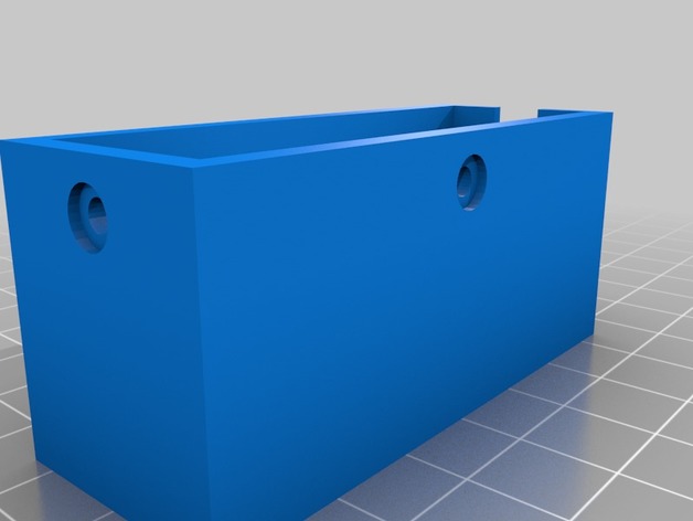
Questo è il progetto 3D pronto per la stampa di un contenitore per modulo Wi-Fi nRF24L01, corredato di antenna esterna del tipo “long-range” e del modulo addizionale di alimentazione a 5V.
Its usefulness lies in keeping the two circuit boards that together make up the nRF24L01 Wi-Fi transmit/receive system — namely the nRF24L01 module itself and its 5V power board — firmly secured and protected, while also acting as a mount for the "long range" antenna.
It can easily be mounted to any platform using the screw holes on the bottom, with or without standoffs.
The lid is secured to the box with a single screw. For other adaptations, get in touch with me and I'll try to provide you with modified print files.
What is this project for?
I should mention that this small enclosure became necessary as soon as I received the 5V power modules for the nRF24L01, like the one shown in the photo below.
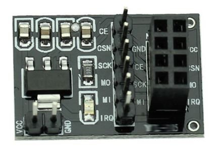
Once I'd assembled the two boards in the correct position and screwed on the antenna, I quickly realized that the length — and therefore the weight — of the nRF24L01 module (which you can see below)
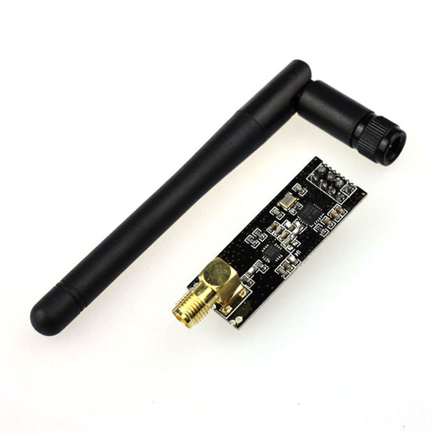
made the whole assembly unstable and fragile, often causing the nRF24L01 module itself to come loose from its socket on the power board.
So they needed to be secured and kept together, safe from knocks or possible damage. Hence the idea of designing and printing a custom-fitted enclosure.
After carefully measuring the dimensions of both boards and the antenna, I modeled them in 3D using CAD software. I then designed an enclosure that would house all the hardware components, adding suitable micro-tolerances.
Finally, I exported the various parts of the enclosure — the container and its lid — as stereolithography (.stl) files, which are shared below and ready for printing.

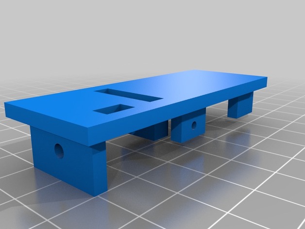
Print settings for the nRF24L01 enclosure:
Reference printer:
Anycubic Kossel Linear Plus
Rafts:
No
Supports:
No
Resolution:
0.2
Infill:
30%
Notes:
I recommend heating the print bed to 60°,
I set the print speed to 80%.
Optional:
6 viti o bulloni formato M3 per fissare il box ad una base e per assicurare il coperchio al box più saldamente.
Assembly instructions:
After printing the two parts (box and lid) of the nRF24L01 enclosure, take a kit of 8 Male/Female DuPont jumper wires for breadboards (like the ones in the photo below)

in the color sequence from brown to gray, and pass the female ends of the brown and red jumper wires through the smaller rectangular hole on the box's lid. Then insert the remaining six jumper wires from their "female" end (the ones colored from orange to gray) through the larger rectangular hole on the same box lid.
Plug the female DuPont terminals onto the two pins of the smaller module: red for (VCC) and brown for (GND).
Now plug in the remaining six pins, from gray to orange, as shown in the following image:

Now, lay the two boards, joined together, into the box, lining up the narrower neck of the gold-colored radio antenna with the U-shaped notch on one side of the box.
Pass the red and brown DuPont wire pair through the smaller rectangular hole in the lid, and the remaining wires through the larger rectangular hole.
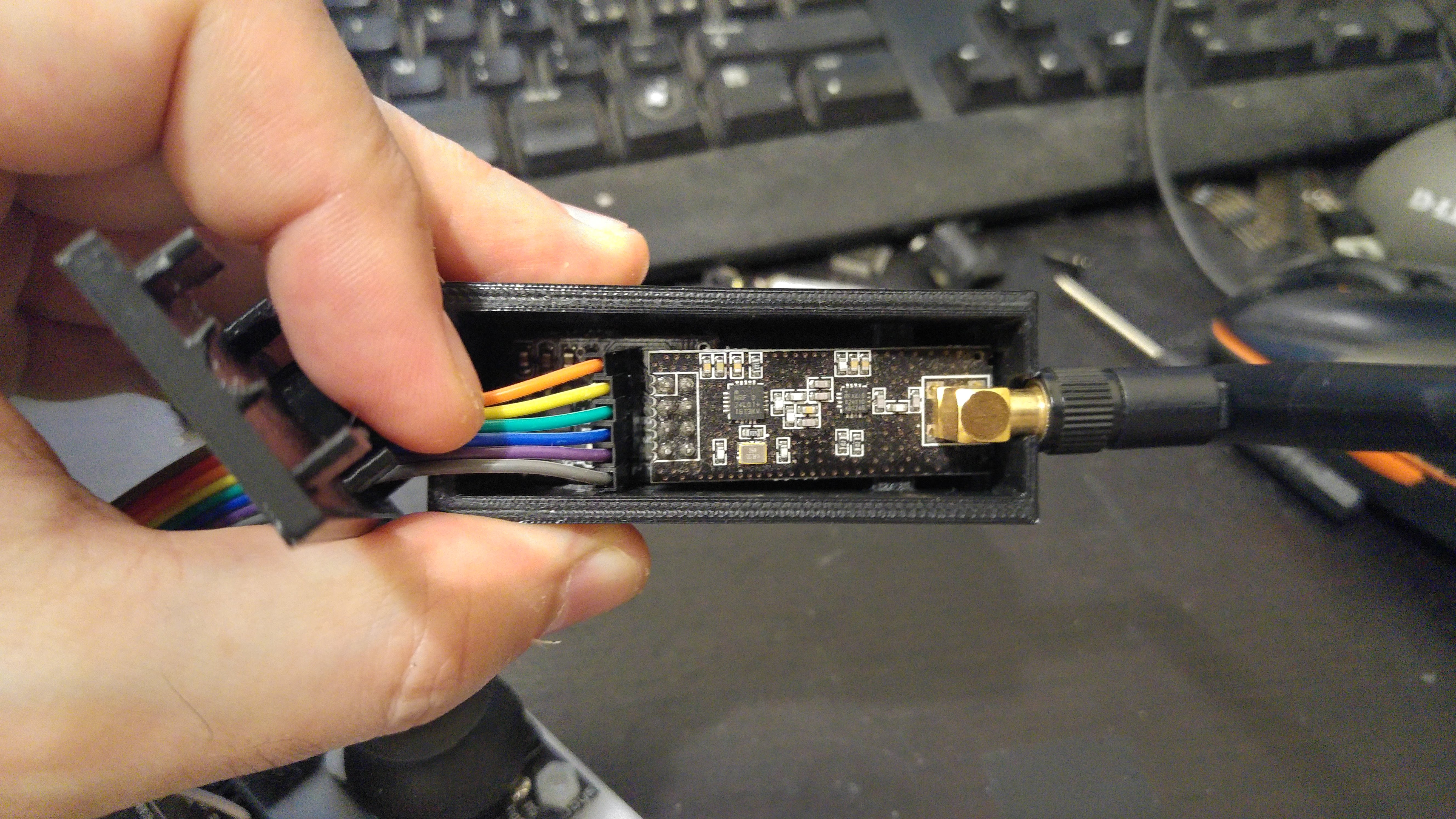
Now that everything is in place, you can close the box with its lid, after aligning it correctly, applying gentle pressure.
Finally, insert the three mounting screws into their holes (one at the front and the other two on the sides).

All that's left now is to give you the download links for the print-ready .stl files:
Slim Box enclosure.zip
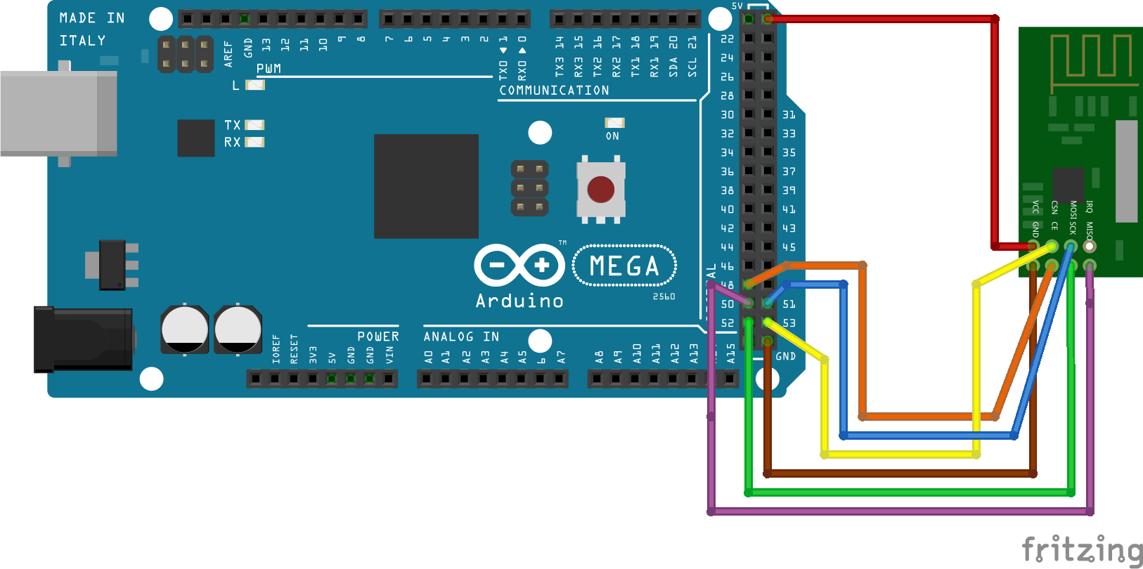
Wiring diagram for the nRF24L01 Wi-Fi module to the Arduino Mega 2560 R3
Nota Bene: Considera che nello schema Fritzing che segue, la nomenclatura e i colori dei cavetti Dupont sono esattamente gli stessi del cablaggio del modulo di potenza illustrato per immagini sopra, ma devi considerare che il modulo di potenza presenta i cinque pin di collegamento CE (Arancione), CSN (Giallo), SCK (Verde), MOSI (Blu), MISO (Viola) tutti in sequenza su una stessa linea ideale e in disparte più in basso sulla destra VCC (Rosso) e GND (Marrone).