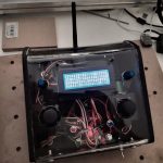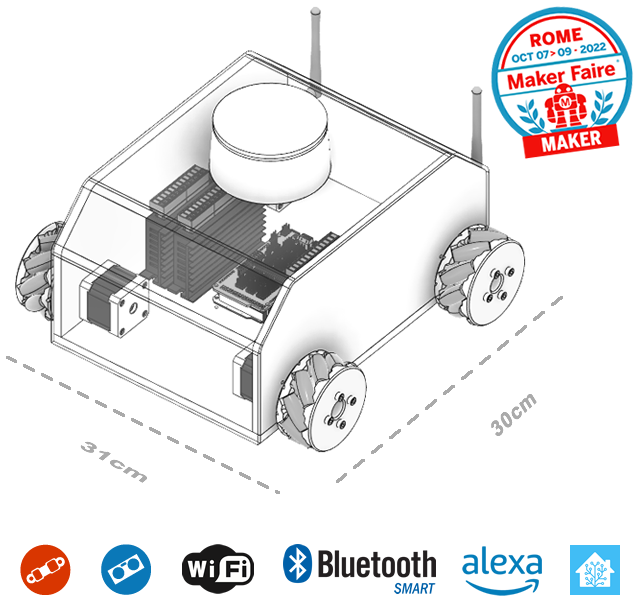
PURPOSE OF THIS GUIDE:
- To build a Personal Home-Automation Robot Multi-role, which we will refer to for brevity as "PEDRO" (PErsonal-Domotic-RObot).
This robot will be autonomous and/or radio-controlled, and will be based on Arduino Mega 2560 R3 and Espressif ESP8266.
PEDRO will be equipped with Mecanum wheels and connected via home Wi-Fi and the MQTT protocol to Home Assistant, the most widely used open-source home-automation hub in the world. The latter will be configured so that it can also autonomously send commands to the robot, through integration with the Amazon Alexa and Google Home voice assistants.
Finally, this guide will show you how to include your own custom commands within scripts or automations that can also be triggered by voice commands, and will explain how to graphically display the robot's telemetry data.
DIFFICULTY LEVEL: medium-high
- Even though this robotics project's difficulty level is medium-high, it calls for a range of hands-on skills and a certain amount of equipment. After all, we're building an autonomous robot with advanced features starting completely from scratch — that is, from its basic hardware and software components. In other words, we'll only buy some of them from our shop or elsewhere; the rest we'll need to make ourselves with the right tools.
Building the home-automation robot requires:
- Basic skills in cutting, drilling and cold-gluing plywood sheets,
- Experience cutting, heat-bending and drilling acrylic (plexiglass) sheets,
- Knowing how to use a soldering iron, needed to solder the power cables to the XT60 connectors and switches,
- Optionally, some parts can be 3D printed, such as the omnidirectional Mecanum wheel components or the small enclosure for the nRF24L01+ module.
As always when working with electronic components, we strongly recommend reviewing the technical diagrams supplied with the project several times, to fully understand how to make the connections between the various elements BEFORE connecting the devices to the power source.
Basic knowledge of the following is also required:
- Arduino, il microcontrollore più diffuso al mondo, e del suo IDE o ambiente di sviluppo,
- Raspberry Pi4/Pi3B+, un computer a scheda singola sviluppato nel Regno Unito dalla Raspberry Pi Foundation,
- Definizione di un “Hub domotico” as Home Assistant (Core 2022.5.5) utilizzato in questo progetto,
- Impostazioni avanzate del firmware del proprio router Wi-Fi.
- Che cos’è una batteria ai Polimeri di Litio (LiPo), come si maneggia, come si ricarica e quali precauzioni adottare nell’uso.
TOPICS COVERED:
- Che cos’è e come funziona il protocollo MQTT tra i protocolli più diffusi nei sistemi domotici e/o robotici come in questo caso.
- Nozioni di base sull’ambiente di sviluppo di Arduino (IDE Arduino) nonchè su uno dei suoi kernel alternativi più diffusi, ovvero FreeRTOS,
- Installazione e configurazione hardware e software del microcontrollore Wemos Mega 2560 R3 e del chip Wifi Espressif ESP8266 integrato,
- Preconfigurazione ed installazione dei 4 driver TB6600 per motori Passo Passo (driver stepper motor),
- Setting up a home-automation hub such as Home Assistant on an SD card and Raspberry Pi 4 / Pi 3B+,
- Attivazione e configurazione dei Componenti aggiuntivi di Home Assistant, ovvero: Duck DNS, File editor, Grafana, Home Assistant Google Drive Backup, InfluxDB, Log Viewer, Mosquitto broker, Samba share, SSH & Web Terminal, HACS, Alexa Media Player.
- Methods and procedures for charging and balancing the cells of a Lithium Polymer battery.
RAW MATERIALS AND TOOLS USED:
- Plexiglass, 600x600x4mm (2 sheets),
- Plywood, 500x500x8mm (2 sheets),
- Alluminio 50x50x200x2mm (2 profilati a L),
- Electrical terminal crimping tool,
- Scissors or wire-stripping pliers,
- Wire cutters,
- Threaded rivet nut tool, with M3, M4, M5, M6, M8, M10, M12 rivet nuts for 2-3mm thicknesses,
- Jigsaw for cutting the plywood panels,
- Cutter or electric rotary tool for cutting the plexiglass,
- Utensile per piegare a caldo il plexiglass (istruzioni per realizzarlo qui),
- Trapano-avvitatore elettrico, consigliato trapano a colonna per alcune lavorazioni,
- Stampante 3D e 1 rotolo da 1kg di PETG se intendi realizzare da te alcune componenti (opzionale).
HARDWARE COMPONENTS USED:
- Wemos Mega 2560 R3 con ESP8266 integrato, corredato da Keyestudio Sensor Shield V1 for Arduino Mega,
- Modulo integrato Bluetooth HC-05 con convertitore seriale,
- Modulo nRF24L01+ con convertitore seriale, antenna WiFi 2,4GHz Long Range e modulo di potenza addizionale,
- 2.4GHz 3dBi Wi-Fi antenna, RP-SMA 12cm, U.FL IPX IPEX to RP-SMA, for ESP8266,
- IRF520 MOSFET driver module, 0-24V 5A PWM output, for Arduino,
- Motor Drive Package TB6600 (4 Stepper Driver),
- Nema17 17HS8401 stepper motor, 0.55N.m (4 motors),
- Ruote tipo Mecanum Wheels da 80mm di diametro autoprodotte (qui istruzioni e files 3D stampabili) o acquistate a parte nel nostro Shop (4 Ruote),
- 5000mAh 3S 11.1V 30-45C LiPo batteries (2 LiPo batteries),
- UBEC, 8A max 15A,
- XT-60 male connector,
- Terminali elettrici da crimpare ai cavi per una connessione stabile e sicura alle morsettiere degli stepper driver,
- Interruttore switch ON-OFF,
- Portafusibile e fusibile per automotive da 15A,
- 1m x Cavi 14 AWG Rosso e Nero e 1m x Cavi 18 AWG Giallo e Nero per le connessioni di alimentazione,
- 4X20 Cavi Dupont F/F e F/M,
- 1 LED RGB a 4 poli con Anodo Comune,
- Set of hex-socket screws, washers and nuts in various sizes: M2, M3, M4, M5, M6, M8, M12,
SOFTWARE COMPONENTS USED:
- Sistema operativo Windows 11 o analoghe distribuzioni,
- IDE Arduino 1.8.16 con le relative librerie necessarie al progetto: Arduino FreeRTOS, ArduinoJson 5.13, Arduino WiFi Link Library (Fork Jandrassy), PubSubClient, OneWire, AccelStepper, SPI, RF24, Adafruit PWM Servo Driver Library,
- Home Assistant,
- I componenti Home Assistant “Alexa Media Player“ e “Notification“, opzionali,
PREREQUISITES:
- Un PC Workstation o notebook con Windows 10/11 installato e funzionante,
- Una rete Wi-Fi con Router accessibile via connessione LAN o Wi-Fi,
- Uno smartphone di ultima generazione con sistema Android, Bluetooth e Wi-Fi per controllo robot e telemetria (opzionale),
- Infine un saldatore o stazione saldante 2in1 con pistola ad aria calda per guaine termorestringenti,
PHYSICAL DEVICES USED:
- PC con Sistema Operativo Windows 10/11 per la programmazione e la compilazione dei Firmware Arduino Mega 2560, per l’installazione e la configurazione dell’Hub Domotico Home Assistant,
- Raspberry Pi4/Pi3B+ con MicroSD da 32/64 Gb e relativo adattatore USB, sul quale girerà il sistema operativo di Home Assistant corredato di tutti i componenti software aggiuntivi,
ACCESSORIES AND EXPANSIONS:
- Amazon Echo (qualsiasi modello o qualsiasi modello di smart speaker che monti Amazon Alexa come assistente integrato), (opzionale),
- Radiocomando Fanbotica LongCom X1 basato su Arduino Nano e modulo ricetrasmettitore nRF24L01+ PA LNA RF con Antenna 2.4 GHz 1100m e Regolator adattatore 3.3V, qui il tutorial per auto-costruirtelo o il link per ordinarne il kit disponibile anche pre-assemblato, (opzionale),
- Braccio Robotico con 6 gradi di libertà, stampato in 3D,
- Torretta LIDAR,
- SLAM System,
- Pan-Tilt con cannoncino laser e dissuasore,
GUIDE INTENDED FOR:

NOTES AND DISCLAIMER
- Any modification you carry out yourself is done entirely at your own risk and responsibility (the contents of this page are for educational purposes only);
- Furthermore, any self-made modification to a device voids its warranty, approvals and quality certifications.
Revisione guida: 1.0
Abstract
Definition of home automation
The domotica, derivante dall’unione del termine domus, che in latino significa “casa”, e del suffisso greco ticos, che indica le discipline di applicazione, è la scienza interdisciplinare che si occupa dello studio delle tecnologie adatte a migliorare la qualità della vita nella casa e più in generale negli ambienti abitati dall’uomo.
In its technical, physical application, this discipline refers to any system that, through one or more pieces of software, manages and controls (by sending commands and receiving telemetry responses) all the "home-automation objects" — also called "entities" — connected to it over a network, which in turn respond to those commands because they're equipped with actuators, sensors and onboard firmware.
Common examples include roller shutters, the garage door, the water heater's electronic thermostat, the lights in various rooms, the TV, the stereo, and so on.
Definition of robotics
The robotica è la disciplina dell’ingegneria che studia e sviluppa metodi che permettano a un Robots di eseguire dei compiti specifici riproducendo in modo automatico il lavoro umano.
We asked ourselves whether it was possible to build a home-automation robot at home!
Ci siamo più volte chiesti se allo stato di sviluppo attuale della tecnologia delle due discipline, ovvero con la diffusione di software sempre più stabili e condivisi sia per la domotica che per la robotica, come ad esempio del celebre Hub Domotico Home Assistant, e dell’ambiente di sviluppo o IDE Arduino, non fosse possibile realizzare un robot domotico, partendo da ciò che è largamente a disposizione dei maker di tutto il mondo, ovvero le piattaforme di prototipazione rapida come lo stesso Arduino e i chip pensati per l’IOT come l’ESP8266 of the Espressif Systems, caratterizzati da Wi-Fi integrato a basso costo, supporto completo al protocollo TCP/IP e funzionalità da microcontrollore.
So, since we managed to build both the home-automation robot and this tutorial, the answer can only be: "Yes, it's possible!"
A compendium for building a true home-automation robot
Sicchè questo vero e proprio compendio sulla interazione tra robotica e domotica guiderà il lettore passo dopo passo nella realizzazione di un robot domotico del tutto autonomo, ma che sarà possibile radiocomandare da uno smartphone via Bluetooth, from a radio RC, o da una apposita interfaccia di Home Assistant.
"But what exactly would a robot integrated into our home's automation software be good for?"
Direi che la risposta più giusta dovrebbe essere: “A tutto ciò che una piattaforma robotica semovente potrebbe servire in una casa e nei suoi ambienti circostanti”, ma così avremmo detto tutto e niente, dunque per scendere ancor di più nel dettaglio mi spingo a citare soltanto alcuni esempi di utilizzo più comuni che vanno dall’agente di sorveglianza H24, al rilevatore di calore, luce, gas, polveri, radioattività, dalle mansioni svolte da un cameriere a quelle di receptionist e portavivande, dalla guida e assistenza agli anziani al ruolo di spazzino in giro per la casa o di tagliaerbe, insomma ci siamo capiti gli utilizzi sono limitati soltanto dalla tua fantasia e dalla dotazione hardware e software!
You'll be able to control your PEDRO home-automation robot even from the other side of the world.
Among the countless features built into your home-automation robot you'll also find one that lets you know in real time what PEDRO is doing, and — more importantly — if you've enabled the surveillance features with a dedicated webcam system, you'll be able to know what's happening in your home even remotely, right from your smartphone, through the Home Assistant app.
Let's get started
- Preliminary steps
- Preparing the work area
- List of the home-automation robot's hardware components
- Sourcing or buying the plexiglass sheets, plywood sheets and aluminum profiles
- Printing the cutting guides in A2 format, 1:1 scale
- Installing and configuring all the necessary software
- Downloading the Arduino IDE from the official site
- Installing and/or configuring the Arduino IDE on our PC
- Installing the required Arduino libraries
- Looking at the differences between our Wemos Mega 2560 board and the Arduino Mega 2560
- The Wemos Mega 2560's communication ports
- Installing the CH340G driver
- Notes on the Arduino WiFi Link Library (Jandrassy fork)
- Installing the Arduino WiFi Link Library (Jandrassy fork)
- Selecting, configuring and verifying the generic ESP8266 board
- Uploading the ArduinoFirmwareEsp.ino firmware to the ESP8266
- Now installing and/or configuring Home Assistant on the Raspberry Pi
- Installing and configuring Home Assistant's add-ons
- Downloading and installing Amazon Alexa on our smartphone and PC and setting up our Amazon Echo device(s) (optional)
- Making all the plywood parts of Pedro's chassis
- Making Pedro's body shell by shaping and bending the plexiglass sheet
- Installing all the hardware into Pedro's chassis
- Doing the wiring and double-checking every connection several times
- Installing the Arduino FreeRTOS firmware on the Wemos 2560
- Building the Long Range Controller
- Running the control tests
Preliminary steps
Before actually getting on with building our Pedro home-automation robot, we need to spend all the time necessary making our work area safe, so as to bring the risk from what we're about to do as close to zero as possible.
The tools we use should be good quality — don't skimp on your toolkit, especially since you'll certainly need it for future projects too.
Safety first! Not wearing protective gear, working in an unsuitable area, or having tools that break easily or, worse, that could injure us or others, is never a good idea!
Preparing the work area
Innanzitutto scegliamo l’area dove opereremo facendo in modo che sia ben illuminata, asciutta, areata e sgombra da oggetti che possano intralciare i nostri movimenti, al netto degli strumenti che utilizzeremo per lavorare.
For example, a hand drill or drill press, a chop saw, and so on, should be arranged on the work surfaces so as to leave enough operating space all around, laid out as sensibly as possible according to the sequence of the various work stages.
Keep the work area tidy and clean before, during and after every work session.
So don't leave wood or metal chips or scraps on the work surfaces during cutting or drilling, since they could easily be thrown at us or at anyone nearby by the rotation or airflow generated by the tools themselves.
For this reason, we strongly recommend using a powerful wet/dry shop vacuum with a sturdy, durable stainless-steel collection tank.
Mandatory safety requirements for the electrical setup
Dal momento che si opererà con strumentazione elettrica è assolutamente necessario che le prese di corrente, gli adattatori, ed eventuali prolunghe siano del tipo appropriato.
Each of these must be able to handle the current load needed to run the tools, and be rated with a comfortable margin against the heat generated in the wires by that current.
Finally, the entire circuit used must be properly grounded.
Personal safety equipment
As with any project involving cutting or rotary tools, it's essential to have:
- Work safety glasses with side shields,
- Cut-resistant work gloves,
- Noise-cancelling work earmuffs,
- Work coveralls are also recommended.
For electronic connections, to avoid damaging the electronic parts:
- Anti-static wrist strap,
- Anti-static gloves.

Getting all the tools needed to build the home-automation robot
All right, it's time to get everything we need to build our home-automation robot!
Pertanto cominciamo dagli strumenti di lavoro che ci serviranno, se non li avete potete trovarli forniti in kit nel PEDRO Tools Workit o in parti sciolte nel nostro shop, pagando un solo costo di spedizione, o anche acquistarli altrove:
- An electrical terminal crimping tool with a good supply of terminals,
- Wire stripper,
- Flat-nose wire cutters,
- Threaded rivet nut tool, with M3, M4, M5, M6, M8, M10, M12 rivet nuts for 2-3mm thicknesses,
- Jigsaw for cutting the plywood panels,
- Cutter or electric rotary tool for cutting the plexiglass,
- Plexiglass hot-bending tool, either purchased or self-made (instructions on how to make one here),
- Electric drill/driver — a drill press is recommended for some steps,
- 3D printer and a 1kg roll of PETG if you plan to make some of the parts yourself (optional).
Here's the list of the home-automation robot's hardware components
Per i componenti hardware necessari al progetto vale lo stesso discorso dei tools, li puoi acquistare già raggruppati nei PEDRO Component kit o singolarmente, risparmiando in ambedue i casi sul costo di spedizione, oppure acquistarli altrove:
- Wemos Mega 2560 R3 con ESP8266 integrato, corredato da Keyestudio Sensor Shield V1 for Arduino Mega,
- Modulo integrato Bluetooth HC-05 con convertitore seriale,
- Modulo nRF24L01+ con convertitore seriale, antenna WiFi 2,4GHz Long Range e modulo di potenza addizionale,
- 2.4GHz 3dBi Wi-Fi antenna, RP-SMA 12cm, U.FL IPX IPEX to RP-SMA, for ESP8266,
- IRF520 MOSFET driver module, 0-24V 5A PWM output, for Arduino,
- Motor Drive Package TB6600 (4 Stepper Driver),
- Nema17 17HS8401 stepper motor, 0.55N.m (4 motors),
- Ruote tipo Mecanum Wheels da 80mm di diametro autoprodotte (qui istruzioni e files 3D stampabili) o acquistate a parte nel nostro Shop (4 Ruote),
- 5000mAh 3S 11.1V 30-45C LiPo batteries (2 LiPo batteries),
- UBEC, 8A max 15A,
- XT-60 male connector,
- Terminali elettrici da crimpare ai cavi per una connessione stabile e sicura alle morsettiere degli stepper driver,
- Interruttore switch ON-OFF,
- Portafusibile e fusibile per automotive da 15A,
- 1m x Cavi 14 AWG Rosso e Nero e 1m x Cavi 18 AWG Giallo e Nero per le connessioni di alimentazione,
- 4X20 Cavi Dupont F/F e F/M,
- 1 LED RGB a 4 poli con Anodo Comune,
- Set of hex-socket screws, washers and nuts in various sizes: M2, M3, M4, M5, M6, M8, M12,
Sourcing or buying the plexiglass sheets, plywood sheets and aluminum profiles
Procuriamoci dal nostro negozio di bricolage preferito 2 lastre di Plexiglass delle dimensioni di 600x600x4mm, ci occorreranno più avanti per realizzare la scocca del nostro robot, ed il coperchio del Long Range Controller.
2 lastre di multistrato in legno da 500x500x8mm con le quali realizzeremo le basi, ed infine 2 Profilati di Alluminio ad L delle dimensioni: 50x50x200x2mm, che utilizzeremo per fissare joystick e top box del controller.
Printing the cutting guides in A2 format, 1:1 scale
Download the PDF files with PEDRO's drawings showing the cutting lines and the crosshairs marking where to drill the mounting holes for the electronic boards, then go to a print shop to have the files printed in A2 format at 1:1 scale — using these templates will make cutting and drilling the plywood elements much more precise and faster.
Preferably have the two cutting templates printed on removable adhesive paper — it'll be much easier to keep the templates in place while cutting and drilling.
Installing and configuring all the necessary software
Next we'll install and configure, on our PC, the software development environment (Arduino IDE), the drivers, the libraries, the firmware, the personal home-automation hub Home Assistant and its add-ons, and finally the Amazon Alexa app.
Downloading the Arduino IDE from the official site
Get the latest version from the official download page. You can choose between the Installer (.exe) and Zip packages. We'll download the former, which installs everything needed to run the Arduino software (IDE) directly, drivers included. With the Zip package, the drivers need to be installed manually. The Zip file is also useful if you want to set up a portable installation.
Once the download is finished, run the installer and accept the driver installation prompt when the operating system shows it.

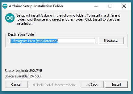

The process will extract and install all the files needed to run the Arduino software (IDE) correctly.
Installing the libraries needed for the home-automation robot project
Per installare le librerie selezioniamo dalla barra del Menu > Sketch > #include libreria > Gestione Librerie.
Nel campo di ricerca della finestra “Gestore librerie” scriviamo “FreeRTOS”, facciamo clic sul pulsante “Installa”,
wait for the Library Manager to finish the installation, then repeat the same steps to install the other libraries, of course typing the following library names into the search box:
- ArduinoJson, > ATTENZIONE: INSTALLARE LA VERSIONE 5.13 E NESSUN’ALTRA!
- PubSubClient,
- OneWire,
- AccelStepper,
- RF24,
- Adafruit PWM Servo Driver Library,
Looking at the differences between our Wemos Mega 2560 board and the Arduino Mega 2560

The Wemos Mega 2560 è un clone della scheda Arduino Mega 2560 R3 combinata con un controller Espressif ESp8266.
Quindi, la scheda le stesse dimensioni del controller originale Arduino Mega.
Il vero e proprio chip microcontrollore è un ATmega2560 as in the Arduino Mega, with 54 pin digitali e 16 analogici, 4 porte seriali UART, un cristallo oscillatore a 16 MHz, una porta USB e un jack di alimentazione, un header ICSP e un pulsante di reset.
Ha tre tipi di memoria: Flash, SRAM ed EPROM. La scheda lavora ad una tensione nominale di 5V e sopporta una corrente massima di 40 mA.
The ATmega2560 controller is moved to the right-hand side, and the ESP8266 controller sits on the left-hand side.
Il connettore USB-A qui viene sostituito con un convenzionale tipo-B con Micro-B, e l’interazione del terminale con i componenti può essere eseguita tramite il convertitore CH340G (connesso RX0/TX0 di ATmega2560) a USB-TTL e l’interruttore DIP 8 contatti.
Wemos Mega specifications
Microcontroller ATmega2560
Operating Voltage 5V
Tensione di ingresso (raccomandato) 7-16V
Corrente in uscita a 5V 1,6A
Corrente in uscita a 3.3V 1A
Digital I/O Pins 54 (of which 15 provide PWM output)
Analog Input Pins 16
DC Current per I/O Pin 20 mA
DC Current for 3.3V Pin 50 mA
Flash Memory 256 KB of which 8 KB used by bootloader
SRAM 8 KB
EEPROM 4 KB
Clock Speed 16 MHz
LED_BUILTIN 13
Length 101.52 mm
Width 53.3 mm
Weight 37 g
The ATmega2560 microcontroller
The microcontroller on the WeMos Mega board is an ATmega2560, a low-power 8-bit AVR RISC chip made by Atmel (now part of Microchip), combining 256KB of ISP flash memory, 8KB of SRAM, 4KB of EEPROM, 86 general-purpose I/O lines, 32 general-purpose working registers, a real-time counter, six timers, PWM, four USART ports, a 2-wire serial interface, 16 channels of 10-bit A/D conversion, and a JTAG interface for on-chip debugging.
The device achieves a throughput of 16 MIPS at 16 MHz and operates between 4.5 and 5.5 volts.
By executing powerful instructions in a single clock cycle, the device achieves a throughput approaching 1 MIPS per MHz, balancing power consumption against fast processing.

Program Memory Type Flash
Program Memory (KB) 256
CPU Speed (MIPS) 16
RAM Bytes 8,192
Data EEPROM (bytes) 4096
Digital Communication Peripherals 4-UART, 5-SPI, 1-I2C
Capture/Compare/PWM Peripherals 4 Input Capture, 4 CCP, 16PWM
Timers 2 x 8-bit, 4 x 16-bit
Comparators 1
Temperature Range (C) -40 to 85
Operating Voltage Range (V) 1.8 to 5.5
Pin Count 100
ESP8266 module
Sulla scheda WeMos Mega è istallato un chip ESP8266 prodotto dalla Espressif, si tratta di un SoC (system-on-a-chip) Wi-Fi integrato con un MCU a 32bit LX106, il chip è collegato al microcontrollore ATmega2560 tramite RX3/TX3.

ESP8266 specifications
802.11 b/g/n
Wi-Fi Direct (P2P), soft-AP
Built-in TCP/IP stack
Integrates the TR switch, the RF amplifier and the antenna
Integrates a PLL, the regulator and a power-management circuit
Output power +19.5dBm in 802.11b mode
Standby current <10uA
The 32-bit CPU can be used to run other applications at the same time
SDIO 1.1/2.0, SPI, UART
STBC, 1×1 MIMO, 2×1 MIMO
A-MPDU & A-MSDU aggregation & 0.4ms guard interval
Wake-up and transmission < 2ms
Sulla scheda WeMos Mega è presente un connettore maschio 7×2 che permette l’accesso diretto ad alcuni pin del chip ESP8266, la funzione è riportata nella parte inferiore del PCB.
| Pin | Function | |
| 1 | VCC | RXD |
| 2 | RST | GPIOO |
| 3 | CH_PD | GPIO2 |
| 4 | TXD | GND |
| 5 | GPIO5 | GPIO16 |
| 6 | GPIO4 | TOUT |
| 7 | GPIO12 | GND |
The Wemos 2560's communication ports
WeMos Mega è in grado di comunicare con un computer, with a Arduino o anche con un microcontrollore. Per fare questo la WeMos Mega mette a disposizione 4 UART hardware per la comunicazione seriale di tipo TTL (5V).
La scheda utilizza come convertitore USB-seriale the chip CH340G, in questo caso occorre installare i driver in quanto non riconosciuto automaticamente dal sistema operativo.
WeMos Mega inoltre è dotato di un ICSP (In Circuit Serial Programming) che permette di programmare l’ ATmega2560 ignorando la procedura di caricamento del codice (ad esempio già sviluppato in un altro ambiente) tramite bootloader; in tal modo si ha la possibilità di sfruttare più memoria sulla scheda, passando da 8 KB a 256 KB.
Altra possibilità data dalla WeMos Mega è il chip ESP8266 che permette il collegamento Wi-Fi il chip è collegato al microcontrollore ATmega2560 tramite RX3/TX3.
La scelta del tipo di interfaccia utilizzare può essere fatta agendo su un gruppo di dip switch presenti sulla scheda
Attraverso la libreria SoftwareSerial è possibile effettuare una comunicazione seriale anche sui pin digitali della scheda.
Wemos Mega DIP switch settings table for choosing the connection type
| Connection | DIP | SWITH 2 | |||||||
|
|
1 | 2 |
3 |
4 |
5 |
6 | 7 | 8 | RXD / TXD |
|
Isolated USB |
OFF | OFF |
OFF |
OFF |
OFF |
OFF | OFF | OFF | RXD0/TXD0 |
|
USB <-> ATmega2560 |
OFF | OFF |
ON |
ON |
OFF |
OFF | OFF | OFF | RXD0/TXD0 |
|
USB <-> ESP8266 (Aggiornamento del firmware o sketch) |
OFF | OFF |
OFF |
OFF |
ON |
ON |
ON |
OFF | RXD0/TXD0 |
|
USB <-> ESP8266 (Comunicazione) |
OFF | OFF |
OFF |
OFF |
ON |
ON |
OFF | OFF | RXD0/TXD0 |
|
ATmega2560 ESP8266 |
OFF | OFF |
OFF |
OFF |
OFF |
OFF | OFF | OFF | RXD0/TXD0 |
|
USB ATmega2560 ESP8266 |
ON |
ON |
ON |
ON |
OFF |
OFF | OFF | OFF | RXD3/TXD3 |
Installing the CH340G driver
La scheda Wemos Mega utilizza come convertitore USB-seriale il chip CH340G invece che il più diffuso chip di FTDI, siccome Windows non supporta nativamente questo chip, il modulo non viene riconosciuto.
Per questo motivo è necessario scaricare il driver dal sito ufficiale del fornitore (sfortunatamente è in cinese).
Once you've unzipped the package, you can go ahead and update the device driver.
Per cui si dovrà lanciare il programma SETUP.EXE.

Dopo l’apertura della finestra si effettuerà l’installazione dei driver, che avverrà in automatico premendo INSTALL.
At the end of the process, the following window will be shown.

A questo punto collegando il modulo, questo sarà riconosciuto e Windows configurerà correttamente la nuova porta COM.

Notes on the Arduino WiFi Link Library (Jandrassy fork)
Prima di installare la libreria “Arduino WiFi Link Library” nella variante riscritta dall’utente Jandrassy, occorre sottolineare alcuni concetti:
La libreria standard “WiFi Link” presente nella raccolta di Arduino non può essere utilizzata in questo progetto in quanto non funzionerebbe con la nostra scheda Wemos Mega 2560 R3 WiFi Esp8266.
La versione Arduino WiFi Link Library (Fork di Jandrassy) permette di utilizzare la porta Seriale 3 of the Wemos Mega 2560 with WiFi Esp8266, vedremo in seguito come utilizzare questa funzionalità.
Per ora rechiamoci a questo link: https://github.com/esp8266/arduino-esp8266fs-plugin/relases e scarichiamo il plugin che ci servirà per caricare files sul file system dell’ESP8266 integrato sul nostro microcontrollore Wemos Mega 2560,
Nella directory della tua cartella degli sketch Arduino, crea una directory “tools” se non esiste ancora.
(You can find the sketchbook folder's location in the Arduino IDE under:
File > Impostazioni > Posizione della cartella degli sketch),
Decomprimi lo strumento nella cartella “tools”,
(il percorso sarà simile a <cartella sketch>/tools/ESP8266FS/tool/esp8266fs.jar).
Restart the Arduino IDE.
Installing the Arduino WiFi Link Library (Jandrassy fork)
Scarichiamo la libreria: WiFi Link Fork Jandrassy
Apriamo o estraiamo lo zip scaricato e copiamo la cartella “ArduinoFirmwareEsp” nella cartella degli schizzi.
Avviamo Arduino IDE e apriamo lo sketch ArduinoFirmwareEsp.ino dal percorso:
File > Sketchbook > ArduinoFirmwareEsp
NOTE: This will also open additional files as tabs in the IDE.

Selezioniamo la scheda “config.h”, portiamoci alla riga 81 e impostiamo il valore di BAUDRATE_COMMUNICATION a 115200,
Impostiamo adesso i Dip-Switch 5,6,7 della scheda Wemos Mega 2560 on ON, e i Dip-Switch 1,2,3,4,8 su OFF, e controlliamo che lo Switch di selezione della porta seriale sia impostato su RXD0/TXD0, in breve la modalità appena selezionata ci consentirà di trasferire il firmware ArduinoFirmwareEsp.ino sul file system del chip Esp8266.
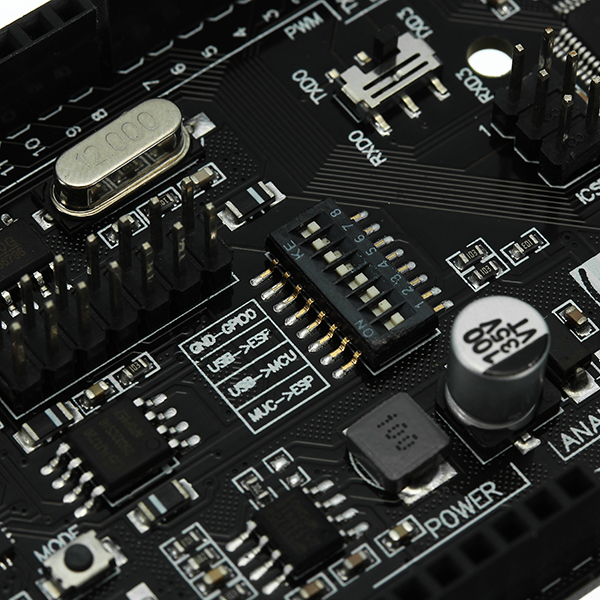
Selezione, configurazione e verifica della scheda ESP8266 generico
Nel menu “Strumenti” seleziona le opzioni della scheda e scegli “ESP8266 generico” dalla sezione ESP8266 del menu Schede. Imposta opzioni dipendenti dall’hardware come frequenza cristalli, frequenza flash, modalità flash, dimensioni flash, led, ripristino.
Then choose the ESP8266 usage options:
“CPU Frequency”: consigliata 80 MHz; 160 MHz produce più calore e ha un consumo energetico maggiore
“LwIP Variant”: v2 Higher Bandwidth,
“Debug port”: Disabled,
“Debug level”: Nessuno è l’impostazione di base,
“Flash Size”: for WiFi Link è opportuno “4M (1M SPIFFS)”, almeno 256 kB sono necessari per SPIFFS,
“Erase flash” è nuova nel pacchetto Arduino esp8266 2.4.1. Per preservare SPIFFS e le credenziali WiFi utilizzare l’opzione “Only Sketch”. Se si cambia dal firmware precompilato, se si modifica l’opzione LwIP o dopo un aggiornamento alla nuova versione del pacchetto core Arduino esp8266, utilizzare “All Flash Contents” per cancellare tutti i parametri impostati da Espressif SDK.
Note: Clearing all the SDK parameters can help if you run into Wi-Fi connection stability issues.
Ora verifichiamo lo schizzo con il pulsante “Verifica”.
The first compile after changing the default board will take longer than usual.
Caricamento del firmware ArduinoFirmwareEsp.ino su Esp8266
Colleghiamo la Wemos Mega 2560 R3 WiFi Esp8266 alla USB del nostro PC con il cavo USB in dotazione.
Utilizzare il pulsante “Carica” nell’IDE per caricare il Firmware WiFi Link.
Una volta ultimato il caricamento del Firmware WiFi Link, impostiamo i Dip-Switch della Wemos Mega 2560 R3 in questo modo: 3, 4 su ON, e 1, 2, 5, 6, 7, 8 su OFF, questa è la modalità che ci servirà a breve per caricare il Firmware dell’ATMEGA 2560, il software che fungerà da sistema operativo del nostro robot domotico.
Installing and/or configuring Home Assistant on the Raspberry Pi
Home Assistant è il uno tra gli HUB personali ideali per realizzare una propria domotica personale in modo organico e funzionale.
Prima di avviare il Raspberry Pi, è necessario “installare” il sistema operativo sulla microSD, la quale è il corrispettivo dell’Hard Disk in un comune personal computer.
L’opzione più semplice per installare un’immagine su una microSD o su un disco esterno USB è quella di utilizzare un semplice tool ad interfaccia grafica.
Nel nostro caso utilizzeremo Raspberry Pi Imager, un tool per Windows, macOS e Ubuntu realizzato dalla Raspberry Foundation il quale è in grado di scaricare l’immagine da Internet, permettendoci di scegliere tra varie distribuzioni (oppure usare un’immagine ad hoc presente sul proprio computer), e installarla sulla microSD o su di un disco esterno.
The procedure we'll follow is this:
- we download and install the software Raspberry Pi Imager on the support computer;
- inseririamo la MicroSD (utilizzando un adattatore USB) nel computer di supporto;
- eseguiamo Raspberry Pi Imager on the support computer;
- clicchiamo su “Operating Systems“, scegliamo la voce “Other specific purpose OS” > “Home Assistant” > “Rpi x/xxx” (scegliere il proprio modello di Raspberry Pi);
- cliccando su “Choose storage“, selezionare la microSD collegata al computer d’appoggio;
- clicchiamo “Write” per installare la distribuzione;
- wait for the task to finish (it can take up to an hour, depending on the speed of the internet connection — required — and the write speed to the microSD card).
Installing and configuring Home Assistant's add-ons
To give our Home Assistant instance all the features our project needs, we'll install the following add-ons one at a time — we suggest checking each one's official website for further configuration details:
- Duck DNS,
- File editor,
- Grafana,
- Home Assistant Google Drive Backup,
- InfluxDB,
- Log Viewer,
- Mosquitto broker,
- Samba share,
- SSH & Web Terminal,
- HACS.
Installiamo Amazon Alexa sul nostro smartphone e/o sul PC e configuriamo il nostro/i nostri Amazon Echo (opzionale)
Se non la abbiamo già fatto in precedenza procediamo a scaricare ed installare la App Amazon Alexa dal repository Play Store nel caso di Android o dallo Store di Apple nel caso di un IOS. Seguiamo poi la procedura canonica indicata da Amazon per configurare il nostro smart speaker Amazon Echo. Ovvero:
- Tap "Device Settings,"
- then the "+" sign in the top right,
- Ora colleghiamo ad una presa l’alimentatore fornito in dotazione col nostro smart speaker Amazon Echo e colleghiamo l’atra estremità aquest’ultimo,
- Clicchiamo su “Aggiungi Dispositivo” Echo, Casa Intelligente e Accessori dal menu che compare in basso,
- finally, after entering the requested information, wait for the device discovery and setup process to finish.
Ripeti le operazioni dal punto 1 al punto 5 per ogni smart speaker Amazon Echo in tuo possesso.
Integriamo Amazon Alexa as “Media Player” on Home Assistant
A partire dalla versione 0.88 di Home Assistant è necessario creare una cartella contenente i file del componente personalizzato, la quale sarà collocata, a sua volta, dentro la cartella “custom_components” all’interno della cartella principale di Home Assistant (ovvero quella nella quale giacciono i file di configurazione come configuration.yaml).
Scarichiamo dunque il pacchetto di installazione e provvediamo a decomprimerlo: esso conterrà una cartella chiamata “alexa_media” la quale rappresenta la cartella dedicata al componente; dunque copiamola dentro la cartella “custom_components” (laddove quest’ultima non esista, provvediamo a crearla).
ALTERNATIVELY, WE CAN INSTALL ALEXA MEDIA VIA HACS
Dalla versione 1.3.0 di Home Assistant il componente Alexa Media prevede un’alternativa molto più facile per installarlo: quella di utilizzare HACS.
Per farlo è necessario avere installato una tantum il componete HACS e poi:
- entrare in HACS;
- cliccare “Integrazioni“;
- click the three dots in the top right;
- selezionar “Custom repositories“;
- *alla voce “ADD CUSTOM REPOSITORY URL” aggiungere – selezionando la categoria “integration” – il path:
https://github.com/custom-components/alexa_media_player
- infine, tornando alla voce “STORE“, cercare e trovare “Alexa Media Player”, cliccarvi sopra e poi, nella pagina apertasi, cliccare su “INSTALL“. Al termine, riavviare Home Assistant.
*this specific step might no longer be necessary.
Getting the 2FA app code
Before continuing with the integration, you need to set up a 2FA app code.
Il “two-factor-authentication – 2FA” (in italiano “Verifica in due passaggi – 2SV“) è una tecnica sempre più in voga che prevede di autenticarsi a un proprio account Internet non solo tramite username/password, ma anche con un secondo passaggio che, il più delle volte, prevede l’invio di un OTP (one-time-password) via SMS (o altro).
Per utilizzare l’integrazione Alexa Media Player è necessario che tale doppia autenticazione presso l’account Amazon sia attiva sul proprio account.
Colleghiamoci dunque a questo indirizzo e provvediamo alla abilitazione; completiamo la procedura fino al raggiungimento della seguente schermata di riepilogo:
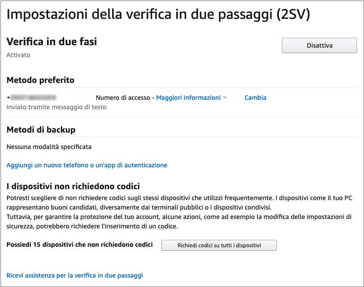
Clicchiamo ora sulla voce “Aggiungi nuovo telefono o un’app di autenticazione“, e poi sul link “Non riesci ad acquisire il codice a barre?” come mostrato nella seguente immagine:

A box will open containing our 2FA app code:
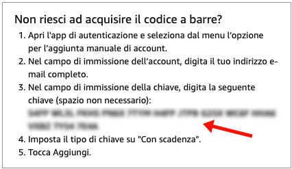
A questo punto segniamoci da parte tale codice (eg. 35T5 LQSY I5IO 3EFQ LGAJ I6YB JWBY JJPR PYT7 XPPW IDAK SQBJ CVXA), servirà a breve. Chiudiamo la finestra.
Once the "Alexa Media Player" component is installed and Home Assistant has been restarted, we're ready to integrate the Alexa devices (linked to our Amazon account) into our home automation.
I dati che ci occorreranno per tale integrazione sono l’username and the Password del nostro account presso il webstore nazionale Amazon (.it per l’Italia, .fr per la Francia e così via).
Dunque andiamo alla voce di menu Home Assistant “Configurazione” > “Dispositivi e servizi” per selezionare la voce “Alexa Media Player”

On the next screen, enter the username, password and the relevant national store into the required fields.
ATTENZIONE: questo è un punto cruciale. Va indicato, per l’Italia, “amazon.it“. Sbagliando questo passaggio ci saranno dei malfunzionamenti a seguire!

Field descriptions:
| Email address | Your email address used to log in to Amazon |
| Password | The corresponding access password |
| Amazon domain region | Impostiamo amazon.it |
| URL to access Home Assistant | Your Home Assistant address |
| 2FA Code | The field previously used for two-factor authorization. Leave it empty. |
| Built-in 2FA App Key | Enter the code previously obtained when activating two-factor verification. |
| Devices to include/exclude | Eventuali dispositivi presenti sul proprio account Amazon, da includere o escludere esplicitamente, divisi da virgola (eg. “Questo dispositivo”,”App Alexa di Marco” eccetera) |
Cliccare su “INVIA” per accedere alla conferma dell’auto-generazione dei codici 2FA da parte dell’app:
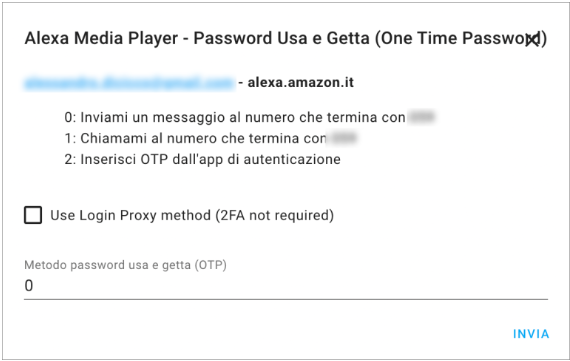
Click "SUBMIT" to move on to the final captcha:

Finally click "SUBMIT" to continue the integration.
At this point the integration will ask you to confirm the authorization sent on Amazon's side, typically via SMS to the phone number associated with the account (or another channel):

Don't click "SUBMIT" right away. First go to the Amazon site (via the link sent by SMS or another channel) and authorize Home Assistant's access:

Once access has been authorized, you can click "SUBMIT" on the window still open in Home Assistant.
A questo punto, se tutto sarà andato bene Home Assistant elencherà i device Alexa collegati al proprio account e quindi, da questo momento, integrati all’HUB:
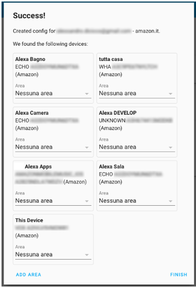
In qualunque momento è possibile consultare il proprio elenco di dispositivi integrati presso la voce di menu “Configurazione” > “Dispositivi e servizi” > “Alexa Media Player“.
Making all the plywood parts of Pedro's chassis
Stick the cutting and drilling templates onto the plywood sheets (500x500x8mm) making sure no air bubbles form; use a ruler as a tool to press the adhesive down as you peel away its backing.
Using a jigsaw or a reciprocating saw, cut along the edges of the shapes shown in the drawing. Remove any rough edges or cutting imperfections with fine-grit sandpaper.
Finally, drill the holes needed to mount the electronic boards using a 3mm wood drill bit.
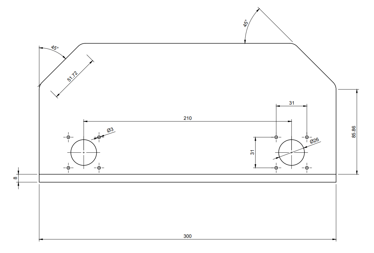

Making Pedro's body shell by shaping and bending the plexiglass sheet
Using a Dremel with a rotary abrasive disc, cut a 940mm x 216mm piece from the plexiglass sheet. This length is greater than what the finished cover actually needs, because the final edges will only be trimmed precisely at the end of this process. We do this because plexiglass can shrink somewhat during hot bending. Work the edges thoroughly with sandpaper — coarse-double grit first, then fine — to remove all imperfections.
Mark the first 2 bend lines on the workpiece at a distance of 100mm from the edge on both short sides, and two more lines further in, at a distance of 61.72mm (51.72mm + 5mm + 5mm) from the previous ones.
The measurements of the 3 segments (the center one plus the two side panels) must match exactly the segments shown in the drawing below, each increased by 10mm (to allow for the bend radius); the two end segments will be 20mm longer, since they'll only be trimmed with a final cut at the end of the process, once the cover has been placed on the chassis and the final cutting lines have been marked.
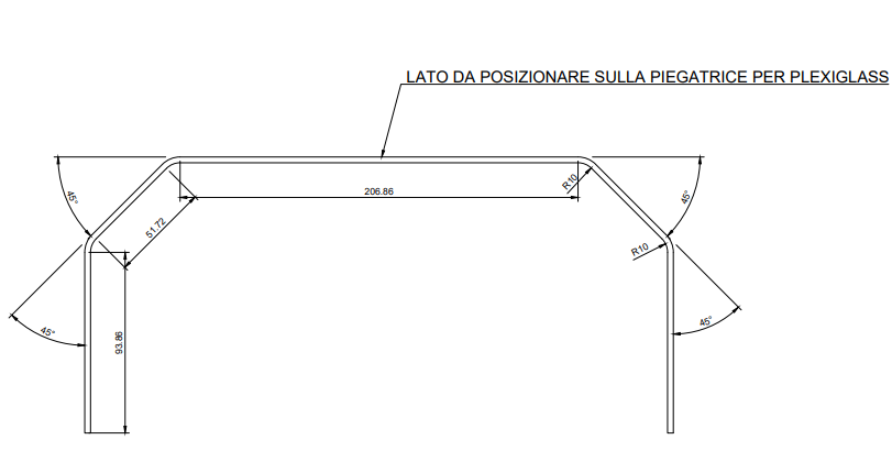
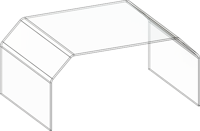
Now place the piece we've just cut onto our plexiglass bender, position it so the section to be bent lines up with the center of the heating element, set the bend angle to 45° using the adjustable protractor bracket, and switch on the bender. Once it reaches bending temperature, slowly raise the rotating table, and once it reaches the protractor bracket's stop, hold it in position for a few minutes with the machine switched off. Repeat this process for every bend needed. Finally, trim the piece with the Dremel and sandpaper after cutting away the excess material at the ends.
In the end we should get a result similar to this:
Installing all the hardware into Pedro's chassis
Before installing the 4 TB6600 stepper driver modules, we need to configure them to set the microstep parameters, the phase current and the peak current for the stepper motors.
A seconda del modello di stepper motor installato dovremo provvedere a configurare gli switch presenti su uno dei lati corti di ogni modulo. Le posizioni ON o OFF dei primi 3 switch presenti servono a configurare la definizione minima del passo (step) del motore in Microstep, secondo le seguente tabella:
| Subdivision | Pulse / circle | S1 | S2 | S3 |
| NC | NC | ON | ON | ON |
| 1 | 200 | ON | ON | OFF |
| 2/A | 400 | ON | OFF | ON |
| 2/B | 400 | OFF | ON | ON |
| 4 | 800 | ON | OFF | OFF |
| 8 | 1600 | OFF | ON | OFF |
| 16 | 3200 | OFF | OFF | ON |
| 32 | 6400 | OFF | OFF | OFF |
gli ultimi 3 invece a configurare la corrente di fase, Current (A), e contemporaneamente la Corrente di Picco, PK Current, secondo questa:
| Average current | Peak current | S4 | S5 | S6 |
| 0.5 | 0.7 | ON | ON | ON |
| 1.0 | 1.2 | ON | OFF | ON |
| 1.5 | 1.7 | ON | ON | OFF |
| 2.0 | 2.2 | ON | OFF | OFF |
| 2.5 | 2.7 | OFF | ON | ON |
| 2.8 | 2.9 | OFF | OFF | ON |
| 3.0 | 3.2 | OFF | ON | OFF |
| 3.5 | 4.0 | OFF | OFF | OFF |
Nel nostro caso si tratta di stepper motors del tipo 17HS8401 con un valore di corrente massima per fase di 1.7 A, dunque gli ultimi 3 switch andranno configurati come ON, ON, OFF. I primi tre impostati per un valore di suddivisione dei Microstep pari a 8, ovvero OFF, ON, OFF. Naturalmente accordate i valori necessari al vostro tipo di motori, potete trovare il datasheet relativo in rete effettuando una ricerca con il nome del modello.
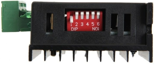
With all the settings made, all that's left is to mount the 4 stepper drivers inside Pedro's chassis, using the mounting holes, hex-socket screws and M3 nuts.

Ora è giunto il momento di installare dei distanziatori esagonali M3 in plastica sotto la scheda Wemos 2560, utilizzando gli appositi fori presenti su quest’ultima e 6 viti a brugola. Successivamente fissiamo la scheda al centro dello chassis di Pedro avvitando ulteriori 6 viti a brugola esagonali dal lato inferiore del pannello stesso facendole passare attraverso i 6 fori predisposti.

Wiring up Pedro and double-checking every connection several times
To make stable, secure connections between the internal electronic parts, we'll make some cables fitted with the appropriate connectors.
Cominciamo a realizzare 8 cavetti maschio/femmina composti ciascuno di 2 fili Dupont (4 con coppie di fili rossi e gialli e 4 con coppie di fili rossi e arancioni), 1 pin maschio ad una estremità di ciascun filo da un lato e un blocco con alloggiamenti per 3 pin femmina dall’altro.
Inseriamo i terminali maschi nelle morsettiere degli Stepper Driver TB6600 e stringiamo le viti dei morsetti per bloccarli al loro interno. Colleghiamo i terminali femmina delle altre estremità alla Sensor Shield seguendo lo schema indicato di seguito.
Terminato il precedente passaggio procediamo ad applicare i terminali elettrici a boccola isolata ai cavi di collegamento tra motori stepper e stepper driver TB6600 e tra batterie Lipo e questi ultimi. Per facilitare il cablaggio distribuiremo in due gruppi cavi con lo stesso colore (giallo o nero) mediante un connettore a due vie di tipo mammut, in modo da ottenere due soli cavi in uscita verso la seconda batteria Lipo.
Finally, to connect the Bluetooth module, the nRF24L01+ module and the LED module to the Sensor Shield, we'll use female/female Dupont wires.

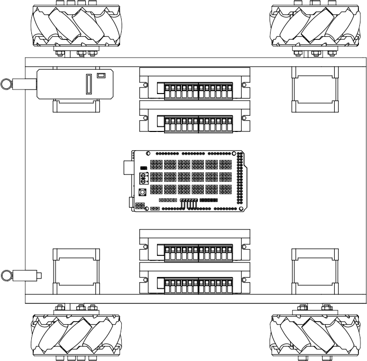
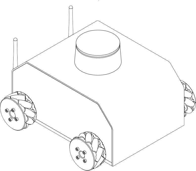
Installing the Arduino FreeRTOS firmware on the Wemos 2560
What is an RTOS?
An RTOS, also known as a real-time operating system, is an operating system designed to meet the requirements of real-time applications. It can process data as it arrives, typically without buffering delays. An RTOS is essentially a combination of predefined function calls.
Introduction to FreeRTOS
Unlike typical real-time operating systems, FreeRTOS is specifically designed for microcontrollers. Since microcontrollers have limited resources, we need an operating system scaled to what's actually available on them. It's an open-source kernel, meaning it can be downloaded for free and used in RTOS-based applications.
Setting up the Wemos to upload the FreeRTOS firmware
Prima di effettuare il caricamento del firmware FreeRTOS sulla Wemos 2560 occorre rimuovere la scheda Sensor Shield V1 precedentemente installata sulla Wemos per accedere più facilmente ai DIP Switch che servono ad impostarne la modalità di comunicazione. Eseguita questa operazione con molta attenzione, cercando di non danneggiare nessun componente, avremo libero accesso ai DIP Switch che imposteremo per la comunicazione USB <-> ATmega2560, quella che ci occorre per trasferire il firmware sulla Wemos 2560 senza sovrascrivere anche la memoria dell’ESP8266.
Per fare ciò imposteremo gli switch da 1 a 8, rispettivamente su: OFF, OFF, ON, ON, OFF, OFF, OFF, OFF.
Now download Pedro's firmware by clicking the button shown below.
All that's left is to connect the USB cable to the Wemos 2560 R3 and upload the firmware by clicking "Upload" on the Arduino IDE toolbar and selecting the file you just downloaded.
Building the Long Range Controller
The Long Range Controller described below is a long-range robot remote control based on the Arduino Nano.
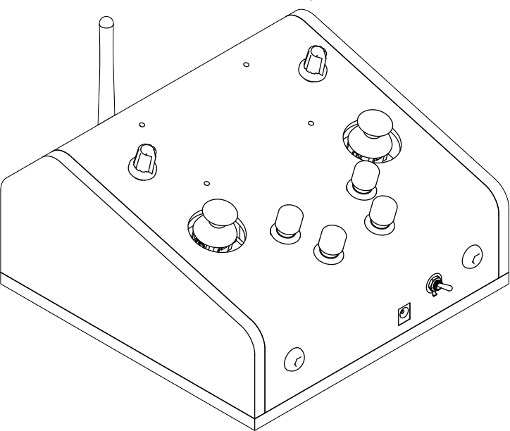
This handy tool for controlling the robot remotely was designed by me to be easy to build using the same materials as the PEDRO robot — plywood and plexiglass — plus a few sections of aluminum profile, some M3, M6 and M8 screws, a small enclosure for the nRF24L01+ module with serial converter, a 2.4GHz long-range Wi-Fi antenna and an additional power module, 2 joystick modules, 2 potentiometers, 4 momentary push-buttons, a 4-line x 20-character LCD module with an I2C module, 3 ON-OFF switches, a 2-cell battery holder, and 2 18650-type batteries.

First, download and print the following PDFs, which will guide us in cutting the 8mm-thick plywood elements, the same type already used to build the PEDRO robot's chassis.
Click the following dimensioned drawing and download the 1:1 scale PDF drawing of the remote control's side panels.

Now do the same for the drawing of the remote control's base:

Once the cutting and drilling of the remote control's side panels and base are done, finish the edges with fine-grit sandpaper.
At this point all that's left is to glue the three pieces together in place with two-part epoxy glue; the final result should look like the following drawing:

From an L-shaped profile measuring 50mm x 50mm x 5000mm, cut three segments: the first one 184mm long, and the other four 50mm long each.


Once you've cut the segments to the right length, drill them following the diagrams' layout.
At this point all that's left is to fit them into the remote control's chassis like this:
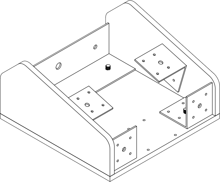
Ora possiamo installare il microcontrollore Arduino Nano con la sua scheda di espansione e il Modulo nRF24L01+ con il suo minibox. Per fissare la scheda al case ci serviremo di distanziatori esagonali in plastica tipo M3. Procederemo con l’introdurre dal lato inferiore della base le viti a brugola M6 attraverso gli appositi fori realizzati in precedenza.

Now let's move on to making the plexiglass cover: cut a strip of plexiglass from our sheet as we did earlier for the robot's cover, and hot-bend it using the plexiglass bender according to the following diagram:
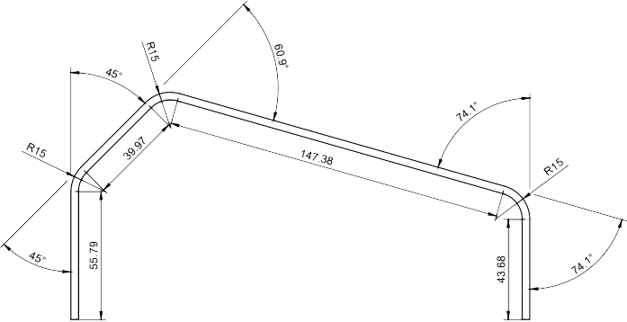
Drill the planned holes into the cover using progressively larger drill bits (hand or drill press) until you patiently reach the hole's final diameter — don't rush, or you risk cracking the plexiglass sheet. Step drill bits are recommended for this task. Finish the job with a file and fine-grit sandpaper.
The final result should look like this:

Infine installiamo i potenziometri, i moduli joystick, i pulsanti momentanei, gli switch, ed infine le viti per fissare la cover di plexiglass al case del radio-controller. Questo è l’oggetto completamente assemblato:
All that's left is to finish up with the wiring, which we'll do following the connection diagram shown below.

Infine scarichiamo il firmware cliccando sul pulsante seguente ed eseguiamo il caricamento dello stesso sulla scheda Arduino Nano collegando quest’ultima al nostro PC con l’apposito cavo USB Tipo B.
LONG RANGE CONTROLLER FIRMWARE