

Rocker Tubie is an affordable, sturdy, modular and eco-friendly 6WD rover.
Rocker Tubie it is a DIY, affordable, robust and modular six-wheeled rover project presented by the Fanbotica team on the occasion ofMaker Faire Europe which was held in Rome from 12 to 14 October 2018, during which it achieved enormous public success.
This wheeled, articulated robot belongs to the general category of self-propelled or remote-controlled wheeled robots also known as "rovers" (wanderers).
Specifically, it is a robot classified as “rover 6WD”, meaning 6-wheel drive.
Build your own Rocker Tubie by reusing 40mm PVC plumbing pipes!
To build the rocker's frame you can reuse PVC plumbing pipes with a 40mm outer diameter.
Tip: You can retrieve them from construction site waste material, directly at the tip, or if you can't find them you can buy them from us in kits starting from December 2018.
In the version presented at Maker Faire you'll need about ten pipe segments of roughly 30 cm each.
But since the project is modular, you could for example decide to double the measurements given in this project's tutorial and get a robot twice as big using the same hardware and the same electronics!
Rocker Tubie DCK (Developer Complete Kit) Part List:
Let's go through the components used to build the Rocker Tubie frame with rocker-bogie suspension:
- 2x PVC pipes, 63 mm,
- 4x PVC pipes, 110 mm,
- 4x PVC pipes, 140 mm,
- 2x PVC pipes, 150 mm.
- 2x PVC pipes, 260 mm,
- 4x PVC fittings, 90° type,
- 4x PVC fittings, 45° type,
- No. 18 PLA moulded fittings (download and print files from here),
- 2x drilled brackets, 98 mm x 20 mm
- 6x 608 2RS skateboard ball bearings, 8x22x7 mm,
- 2x M4 threaded rods, 4mm x 1000 mm,
- 2x M8 threaded rods, 8mm x 1000 mm,
- 61x M8 self-locking hex nuts, 13 mm outer diameter,
- 16x M8 bolts, 13 mm head diameter, 60 mm length,
- 8x M8 bolts, 13 mm head diameter, 80 mm length,
- 61x round washers with M8 hole, 16 mm outer diameter,
- 16x M4 bolts, 4 mm x 60 mm,
- 16x M4 nuts, 7 mm outer diameter,
- 20x heat-shrink tubing sleeves of various sizes,
- 60x M3 hex standoffs, 12 mm tall,
- 6x 12V DC motors, 107 rpm, with gearboxes, Hall-effect encoders and drilled mounting brackets,
- 6x wheels, 130 mm x 60 mm.
And here is the Rocker Tubie's onboard electronics:
- 1x 3S LiPo battery – 11.1V 5000mAh 30-45C (not included in the kits),
- 1x 5A XL4005 adjustable DC-DC step-down power converter,
- 1x Arduino Mega 2560 Rev3 microcontroller,
- No. 1 Motor control board DBH-12V up to 30A 2 channels,
- 4x 10mm full-color RGB LED modules,
- 2x Sharp 2Y0A02 proximity sensors (20-150 cm),
- n°1 modulo Wi-Fi nRF24L01, corredato di antenna esterna del tipo “long-range” e del modulo addizionale di alimentazione a 5 V, (maggiori dettagli qui),
- 1x set of 20 Dupont male/female jumper wires,
- 1x set of 20 Dupont female/female jumper wires,
Technical details of the Rocker Tubie frame
Rocker Tubie + RC Module
The Rocker Tubie's suspension system is similar to that of NASA's rovers used for Mars space missions.
Infatti sono state adottate sospensioni del tipo a bilanciere, per una migliore stabilità su terreni disconnessi.
This suspension technology offers the advantage of keeping at least five out of six wheels in contact with the ground at all times, reducing the chance of the vehicle tipping over to extreme cases only.
The Rocker Tubie also features six independent 130 mm x 60 mm wheels and an equal number of 12V, 107 rpm brushed motors.
A Hall-effect encoder on every motor shaft allows the exact position, rpm, and distance traveled by each wheel to be measured.
Il driver dei motori è un DHB-12V a doppio canale per un max di 50 A con ponte H, al quale abbiamo già dedicato un articolo qualche tempo fa che puoi leggere qui.
In the version with PLA-printed fittings it can support loads of up to 30 kg.
The electronics are managed by Arduino Mega 2560 microcontrollers.
The step-by-step guide
I'm putting together the step-by-step guide for the Rocker Tubie.
In it I'll explain how to make the tubular elements and the 3D-printed fittings, and I'll also walk through the various stages of assembly, wiring, electronics and software installation, along with the related functional tests.
Il progetto è stato selezionato per essere esposto in uno stand dedicato presso la Maker Faire Europe di Roma 2018 che si è tenuta con un eccellente riscontro di pubblico dal 11 al 14 Ottobre nel Padiglione n°6 della Fiera di Roma.
Downloading the STL files to 3D print
Before proceeding with the assembly stages, get everything ready — personal protective equipment and the tools you'll need — and download the STL (stereolithography) files for the parts to be 3D printed from the project's Thingiverse page by clicking here:
Phase 1 – Cutting the PVC pipes
The first step of the Rocker Tubie tutorial is cutting the PVC pipes into sections.
Get two PVC pipes, each two meters long, with a 40mm outer diameter.
Prendendo le misure con un metro rigido segna con una matita i punti esatti nei quali dovrai sezionare il tubo con una tagliatubi a cricchetto o un seghetto con la lama per plastica o metalli.
Tip: wrap paper masking tape around the pipe at the points where you plan to mark the cutting line, so you'll be more precise.
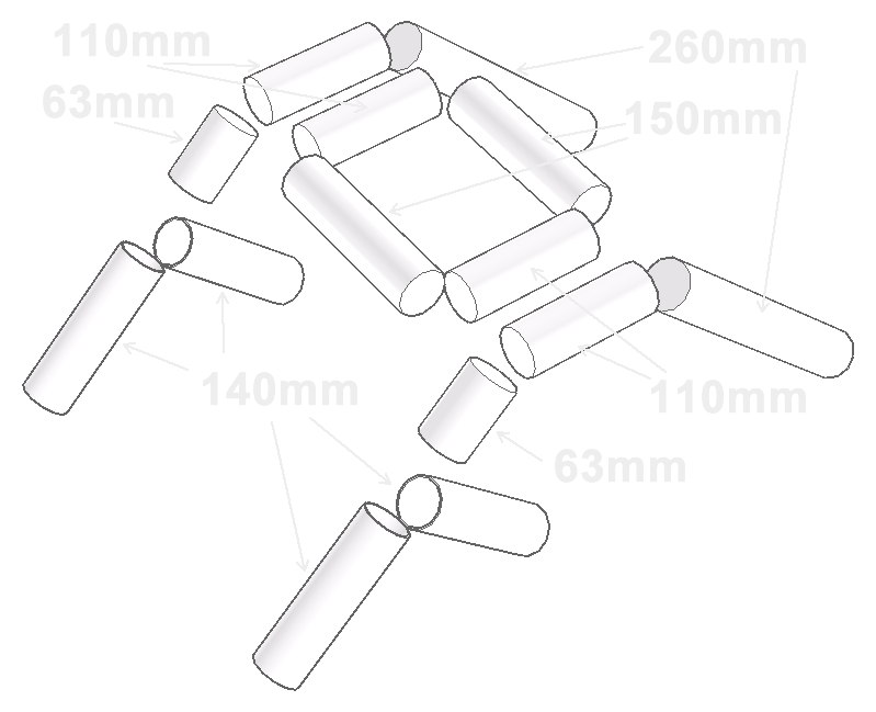
Dimensions of the PVC tubular elements
The outer diameter of the straight PVC tubular elements is 40mm, matching the inner diameter of the fittings we'll look at next.
The dimensions of the various tubular elements to be cut with the pipe cutter from the 2 pipes of 2000 mm each (included in the kit) are as follows:
- 2 x 260 mm (front angled elements)
- 4 x 140mm (long rear angled elements),
- 2 x 63mm (short rear angled elements),
- 4 x 110mm (side horizontal elements),
- 2 x 150mm (front and rear horizontal elements).
How to safely cut with the pipe cutter.
Wear gloves, safety glasses and a protective mask, and cut while keeping the pipe cutter as perpendicular to the pipe as possible. As you work the ratchet, the cutter's blade will start pressing into the pipe's surface until it gives way. Keep cutting with a steady hand and continue until you've cut all the way through the pipe's diameter.
Come accennato anche nell’articolo di descrizione dello strumento tagliatubi, è consigliabile non usare la tagliatubi per tagliare tubi di lunghezza inferiore ai 4 cm, in quanto molto probabilmente in fase di taglio un tubo di così esigua lunghezza cederà col pericolo di generare delle schegge, dunque adoperatela soltanto per tagliare tubi di lunghezza dai 4cm in su.
Once you've cut all the necessary sections, file down their edges with sandpaper — coarse grit first, then fine — until any irregular edges are completely removed.
Phase 2 – Printing the PLA fittings
La stampa dei raccordi in PLA è il secondo step e consiste nella stampa 3d dei 18 raccordi in PLA necessari all’assemblaggio degli elementi in PVC del telaio Rocker Tubie, e delle 4 mascherine predisposte per alloggiare sensori e led.
You'll find them available as print-ready downloads below, or soon you'll be able to order them already printed directly from us.
Gli ultimi tre files disponibili sulla mia pagina Thingiverse per il download, sono gli elementi che servono per l’assemblaggio del modulo superiore con l’elettronica di bordo e le batterie Lipo, del quale parlerò più avanti nel tutorial.
Download the STL files from Thingiverse
Print settings for the PLA fittings
Print settings for PLA filament can vary considerably depending on each printer's characteristics; I'm sharing the ones I used with my Anycubic Kossel Linear Plus printer.
Filament: PLA 1.75 mm,
Resolution: 2 mm,
Heated bed at 60°,
Infill: 60%,
Support: Brim,
Slicing software used: Cura 3.4.0.

Phase 3 – Preparing the PVC pipes and fittings
Drilling the PVC fittings
Before assembling the PVC pipes and the Rocker Tubie fittings, you first need to drill 3mm through-holes in the collar of each PVC fitting, perpendicular to the sides of the Rocker.
Do this for all the PVC fittings (with a 40mm inner diameter).
Ovvero per i 4 raccordi in PVC con curvatura a 45° che serviranno come giunzione tra gli elementi laterali and for i 4 raccordi in PVC con curvatura a 90° che serviranno a congiungere gli elementi centrali del Rocker,

Tip: To drill precise, perfectly perpendicular holes, wrap the ends of the pipes with paper masking tape, and also use it to pencil-mark the exact point where you'll drill the holes on both faces of each fitting.
Drilling the PVC pipes
Proceed in a similar way to drill the PVC pipes exactly in line with the holes already present in the 3D-printed fittings.
That is, wrap the end of each PVC pipe with masking tape, fit a PLA fitting onto that pipe, and pencil-mark the point where the hole is to be drilled on the pipe. Once marked, remove the PLA fitting and drill with a drill bit, first a 4mm one and then an 8mm one.
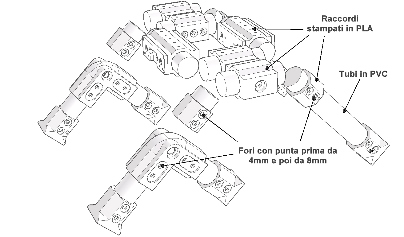
Once you've drilled all the holes in the PVC pipes, remember to remove all the pieces of masking tape.
Painting (optional) the PVC pipes and/or fittings.
At this point, if you feel it's needed, you can go ahead and paint the PVC pipes and/or fittings.
For a good paint job, first spray a coat of primer on all the pipes, then paint them with whatever color you prefer — I chose matte anthracite black, but you can use any spray paint color you think works.
Tip: to paint safely, use a mask, safety glasses and gloves suitable for painting.
Use a piece of cardboard large enough to act as an overspray backdrop for the items being painted. Run a piece of wire through the pipe and tie the ends of the wire to something, so you can hold it suspended horizontally to easily paint every angle of it.
Phase 4 – Assembling the frame and installing the motor cables
Following the fitting-naming diagram below, we'll assemble the elements in sequence from A to Z using the PVC pipes you've already cut, drilled and, if you chose to, painted.
For the pipe diagram with the corresponding measurements, refer to the "Cutting the PVC pipes" section.

Assembling the "A" end pieces
Comincia ad assemblare i 6 terminali “A” (vedi schema precedente), con i 2 tubi da 260 mm e i 4 tubi da 140mm.

Slide the drilled pipe into the "A" end piece, making sure the holes on both sides of the pipe line up with those on the end piece.
Ora inserisci le rondelle nei 4 alloggiamenti predisposti (2 per ciascun lato del terminale), poi inserisci le viti M8 da 80mm nei fori e fissale con i dadi autobloccanti M8 dall’altra parte come indicato nello schema seguente:

Tip: to tighten the bolts into the self-locking nuts, use an adjustable wrench to hold the hex-head bolt still while you use another plain or socket wrench to tighten the self-locking nut.

Routing the motor wiring through the "A" end pieces
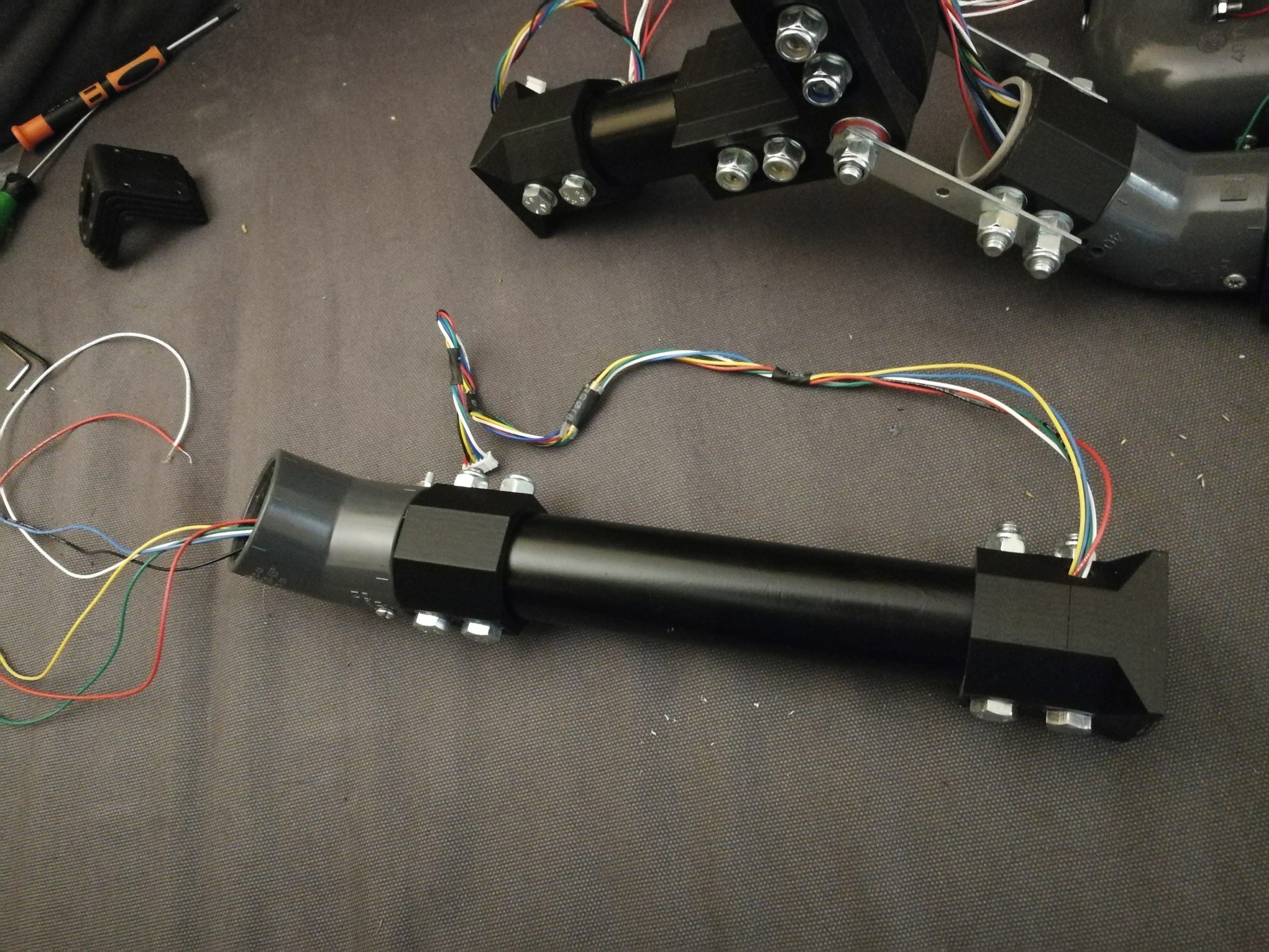
In questa fase del montaggio approfittiamo della facilità di accesso alle cavità dei tubi e dei terminali per posizionare al loro interno i cavi a sei fili che serviranno ad alimentare i 6 motori indipendenti del rover e quindi a ricevere i segnali dei sensori di Hall (encoder) posizionati in torno all’asse sul retro di ciascun motore.
Tip: to easily thread the ends of each 6-wire cable through the side holes on each "A" end piece, coat the holes with gear grease and bundle the wires into a single cable using pieces of heat-shrink tubing about one cm long each, spaced ten centimeters apart, preferably along the whole length of the cable.

Do this for all the "A" end pieces. The final result is shown in the following image:
Drilling the connecting brackets.
Pratica dei fori da 8 mm nelle 2 staffe di raccordo distanziando i punti centrali dei primi due fori di 20 mm e il secondo e il terzo di 58 mm.
Tip: To drill the brackets safely, use a drill press, or hold the brackets steady with a bench vise. Use a metal drill bit, first a 3mm one and then an 8mm one.
Fitting the bearings into the "B" fitting housings
Insert the 4 bearings into their housings (two per fitting).
Tip: proceed very carefully and use a rubber camping-style mallet to seat the bearings into place.
A useful trick is to preheat each bearing with a hot-air soldering tool or a hair dryer before pressing it into place. The polylactic acid (PLA) the fittings are made of is very heat-sensitive and this will let the bearing slide into its housing without difficulty.
Routing the motor cables through the "B" fittings
Before securing the "B" fittings to their respective PVC pipes, don't forget to route the motor cables through the designated holes as shown in the following image.

Assembling the "B" fittings
Once that's done, assemble the "B" fittings as shown in the next diagram.
Note the double washers where the bearings sit.
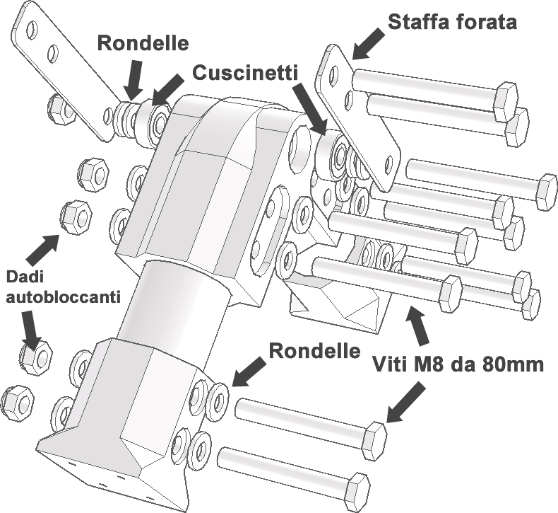
The following image shows the two "A" end pieces and the "B" fitting assembled together:

Motor cable routing through the "C" and "D" fittings, left side

Assembling the "D1" and "E1" fittings, left side


Assembling the "D2" and "E2" fittings, right side

Assembling the "B1" and "C2" fitting brackets, left side

Assembling the sensor mounting plates

Frame assembly complete
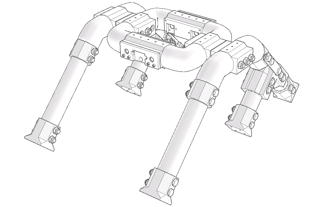
Phase 5 – Installing the brackets and motors
After flipping over your Rocker Tubie's supporting frame so the ends of the 4 3D-printed end pieces labeled "A" in the previous diagrams are clearly visible, hold the motor bracket's flange in position with one hand and secure it to the end piece using the hex socket screws.
Make sure all the brackets have their drilled flanges (for the subsequent motor installation) aligned on the outer right and left sides of the Rocker.

Use an Allen key to drive and tighten the screws into place.
Take your time screwing them into place — there's no need to force anything at this stage.
Repeat this step to attach the remaining 5 brackets to the end pieces.
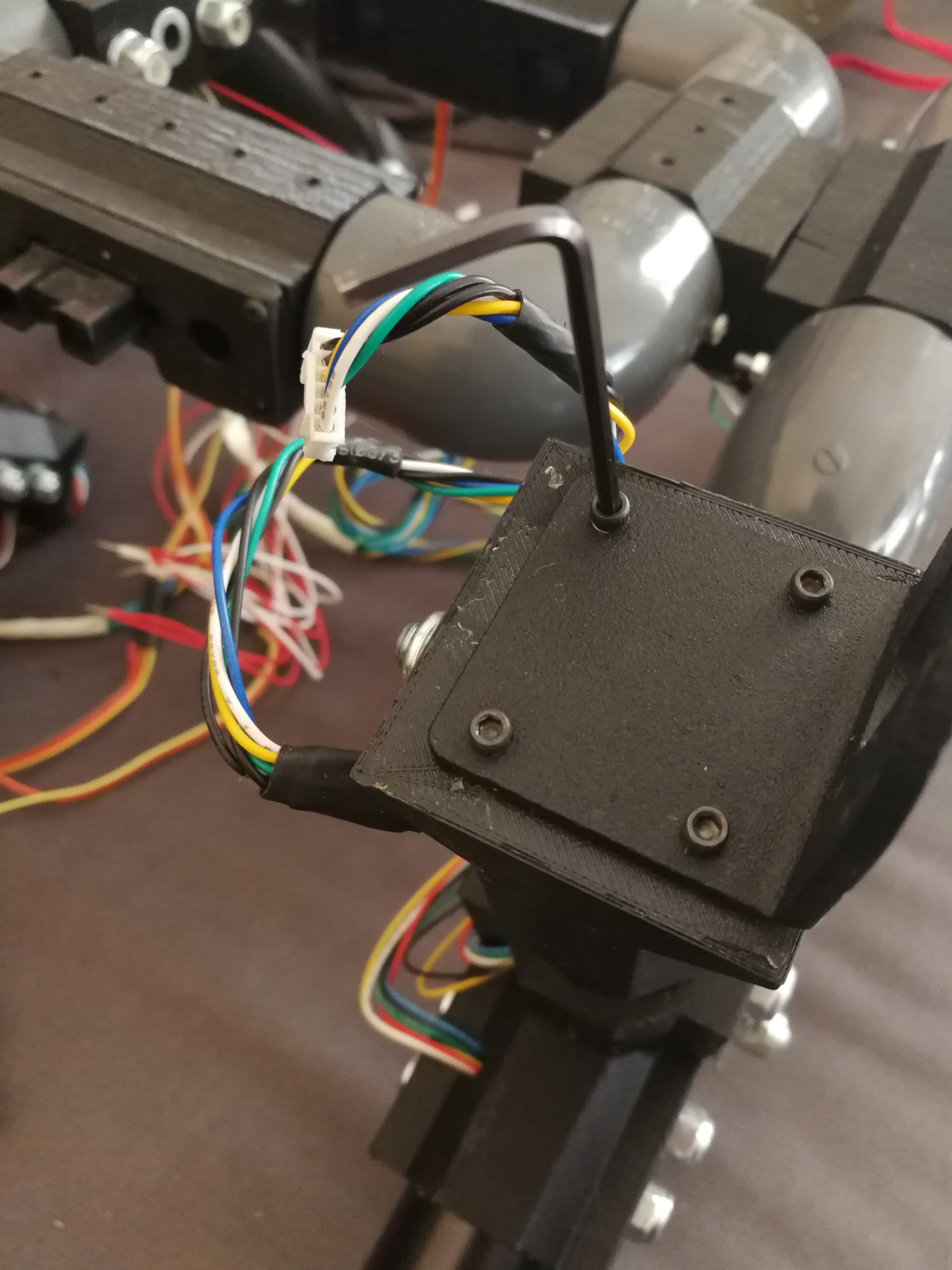
Now position one of the six supplied DC motors into the motor bracket's slot, lining up the threaded holes on the motor body exactly with the flange's through-holes.
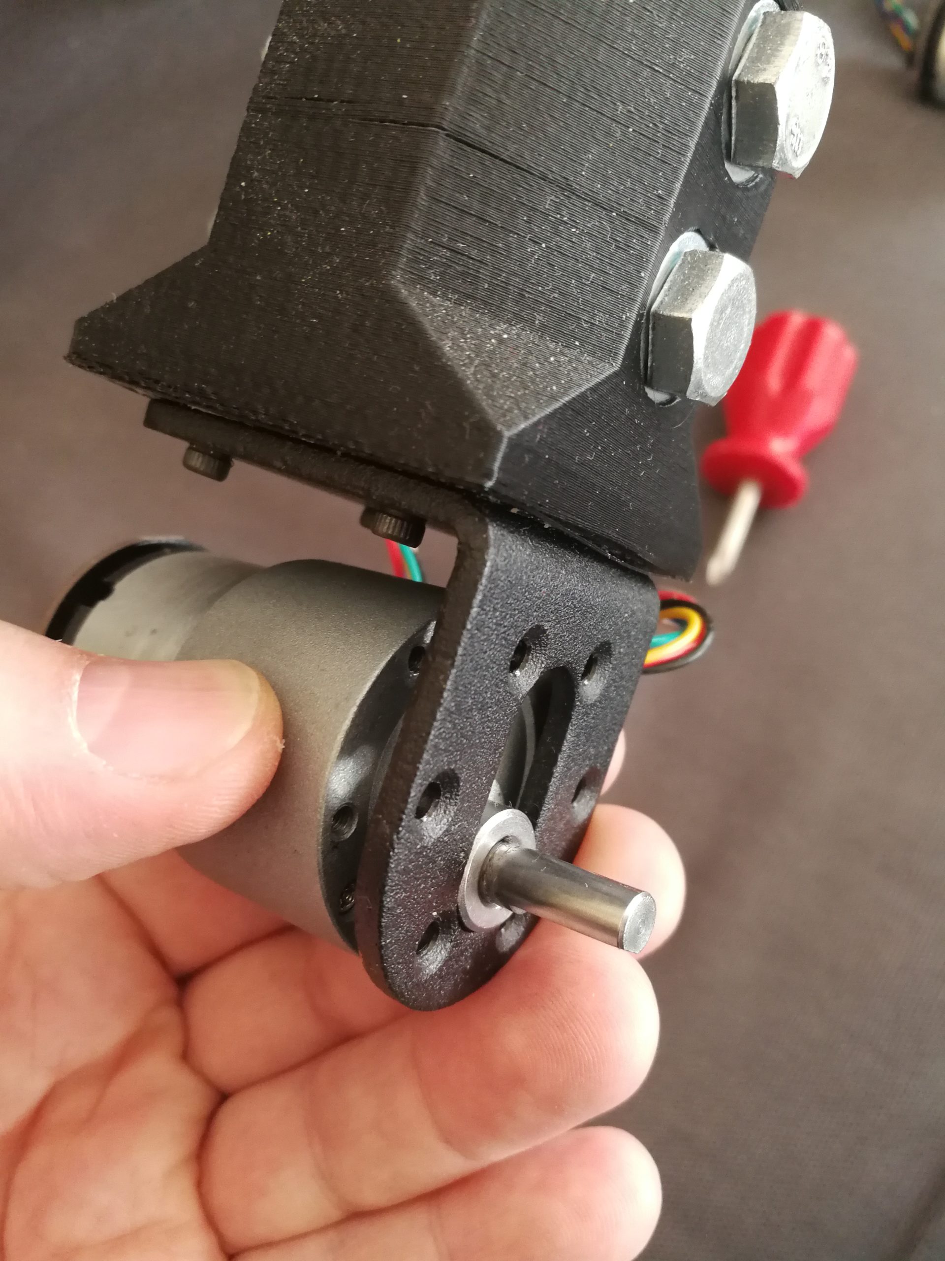
Firmly secure the motor to the bracket by tightening all 6 of the supplied mounting screws.
Repeat this for the remaining 5 motors of the Rocker.

Fit the wheel hub onto the motor shaft, securing the small hex screws with the supplied Allen key into the threads on both sides of the small brass cylinder.

Tighten these small screws firmly, but don't overdo it.

Finally, mount the wheels, securing them to the hubs with the fixing screws included with them in the wheel kit.
Congratulations! You've just finished assembling the 1:8 off-road brackets, motors, hubs and wheels kit for your Rocker Tubie!
Whenever you're ready, let's move on to the final assembly phase, which covers installing the microcontroller, the radio module for receiving commands and transmitting telemetry data, the sensors, and all the other electronic devices that together make up the Rocker Tubie's electronics.
Phase 6 – Assembling and installing the Up-Box, electronics and sensors
Assembling the Up-Box that houses your Rocker Tubie's electronic boards is quick and straightforward.
The Up-Box consists of 2 recycled-aluminum plates, one top and one bottom, and 8 3D-printed side elements.
Simply connect the side pieces, as shown in the following images, using the supplied hex socket-head screws.
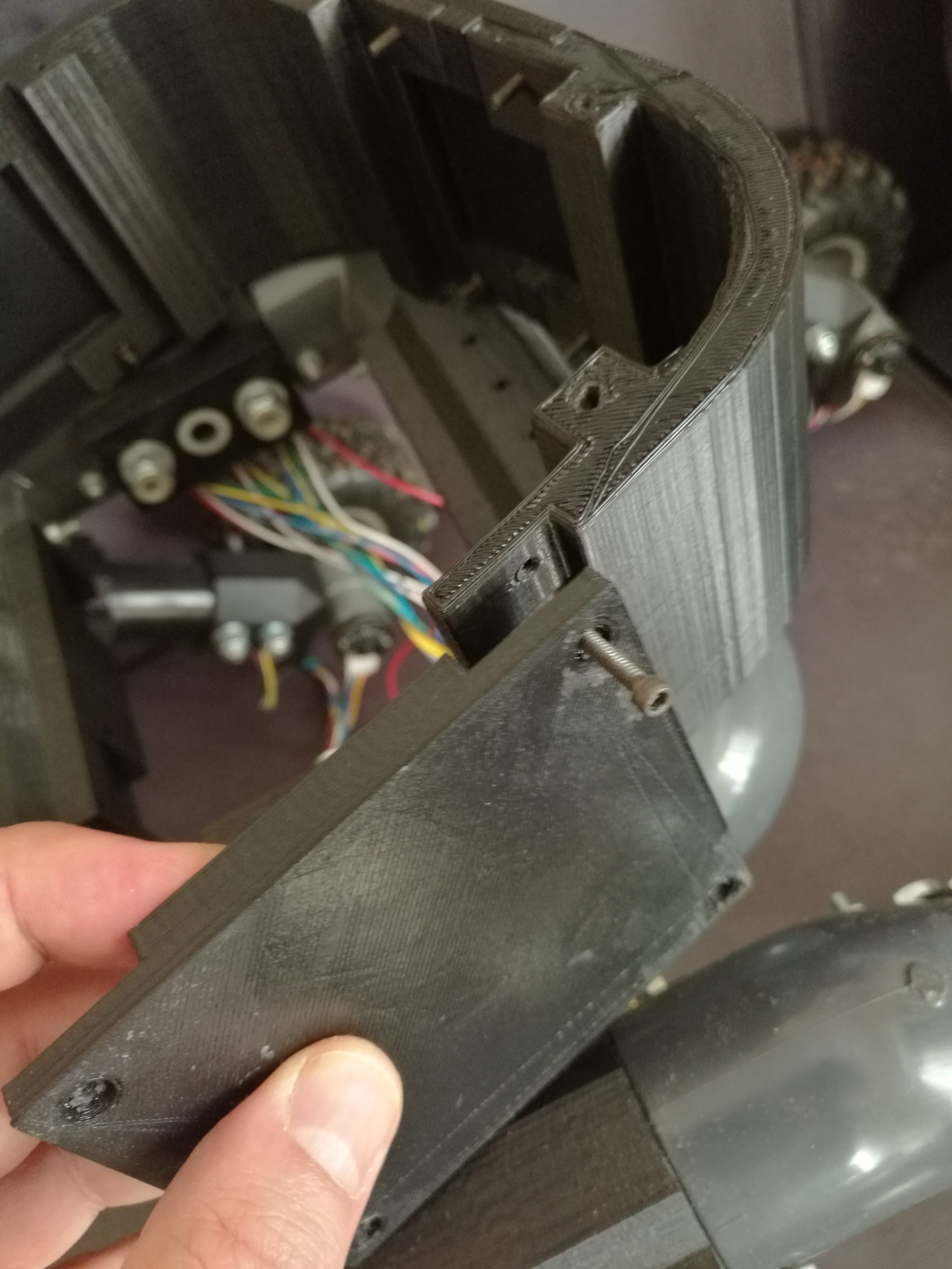
Once finished, the Up-Box's assembled perimeter elements should look like this.
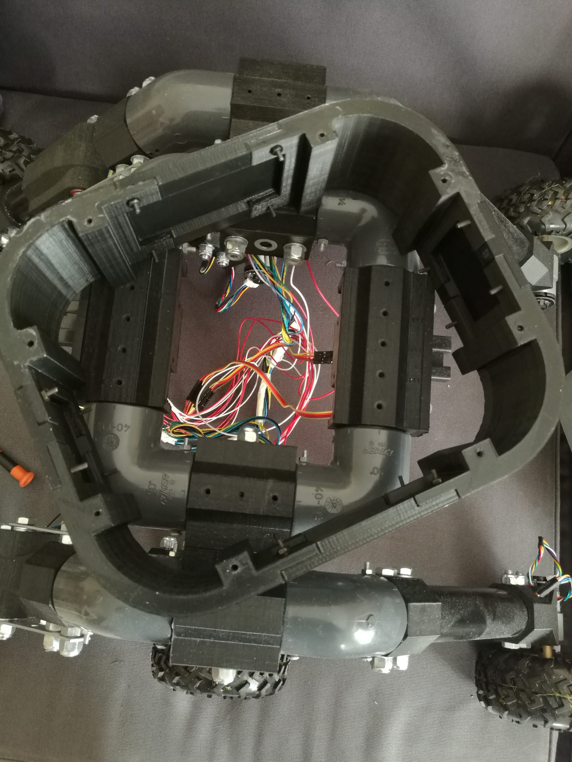
Now install the top and bottom plates, screwing them on with the hex-head screws provided.

From inside the box, insert the supplied M4 threaded rods and screw the plastic standoffs onto them from the bottom side of the Up-Box.
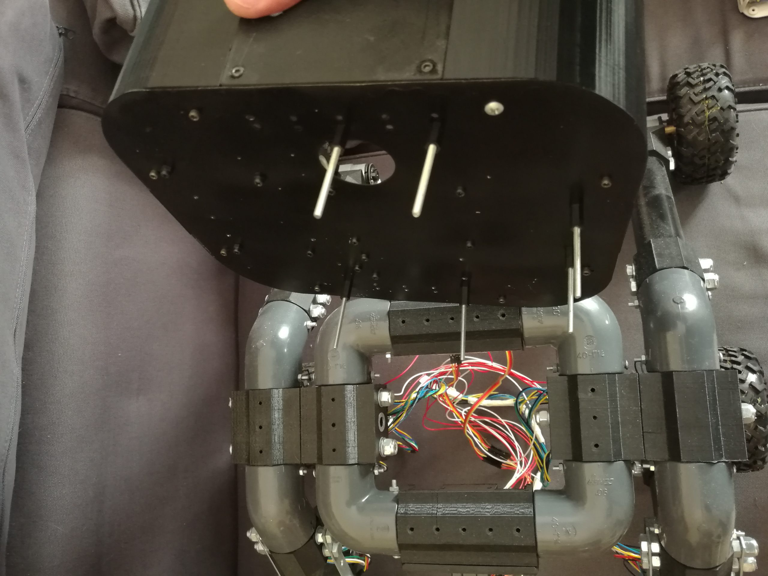
Now place the Up-Box onto the Rocker Tubie, pushing the M4 threaded rods all the way down to the base of the standoffs.

In the following image you can see the Up-Box positioned and secured on the Rocker Tubie; note the M4 plastic standoffs inside it, installed to allow the various electronic modules to be mounted.

We're ready to mount the first electronic board, the Arduino Mega 2560 R3 microcontroller. To make things easier, I recommend first making the connections between the Arduino Mega 2560 R3 and the nRF24L01+ radio module using the supplied Dupont wires, following the diagram shown below.

Abbiamo dedicato un articolo al Modulo Wifi NRF24L01+ nella sua versione in box stampato in 3D che puoi visionare qui

Once you've made the connections between the Arduino Mega and the radio module, you can go ahead and mount both of them.

Note that the aluminum plate forming the base of the Up-Box has a circular hole designed to make it easier to route and connect the cables to the Rocker Tubie's electronic modules.

Allo stesso modo fissa il modulo convertitore di tensione XL4005 ma prima di farlo connetti ad esso i cavetti Dupont e il connettore di uscita dell’alimentazione che in seguito andrà collegato all’Arduino Mega 2560 R3.

Infine installa con la stessa modalità la scheda di controllo motori DBH-12V fino a 30A 2 canali.

Now twist together the ends of the wires coming from the positive terminals of the 3 left-side motors (A), then do the same for the wire ends of the right-side motors (B). Repeat this, but this time with the wires coming from the motors' negative terminals. Now insert the terminals you've made, along with the power supply's positive and negative wires, following this order from left to right: Terminal A (left negatives, left positives), Center terminal (power negative pole, power positive pole), Terminal B (right positives, right negatives).
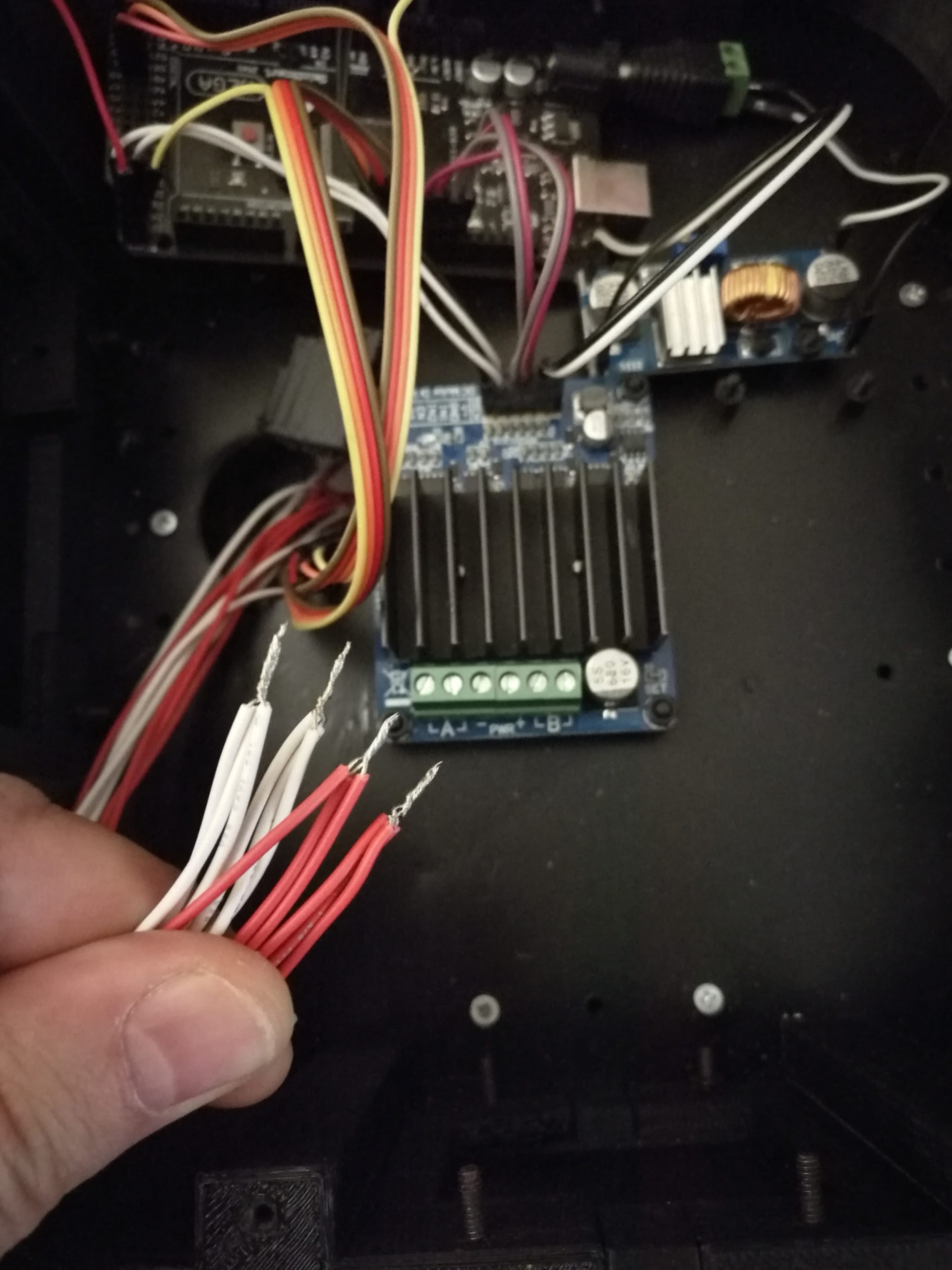
The following image shows the power cables ready to be inserted into the motor driver.
Nota bene: I cavi di alimentazione provengono dall’interruttore a 2 posizioni che per ora va tenuto non collegato alla sorgente di alimentazione (nelle successive fasi di test collegheremo lo stesso alla batteria a 3 celle 11.1V mediante il connettore XT60).

In the end you should have the electronic modules and connections arranged as shown in the following image:
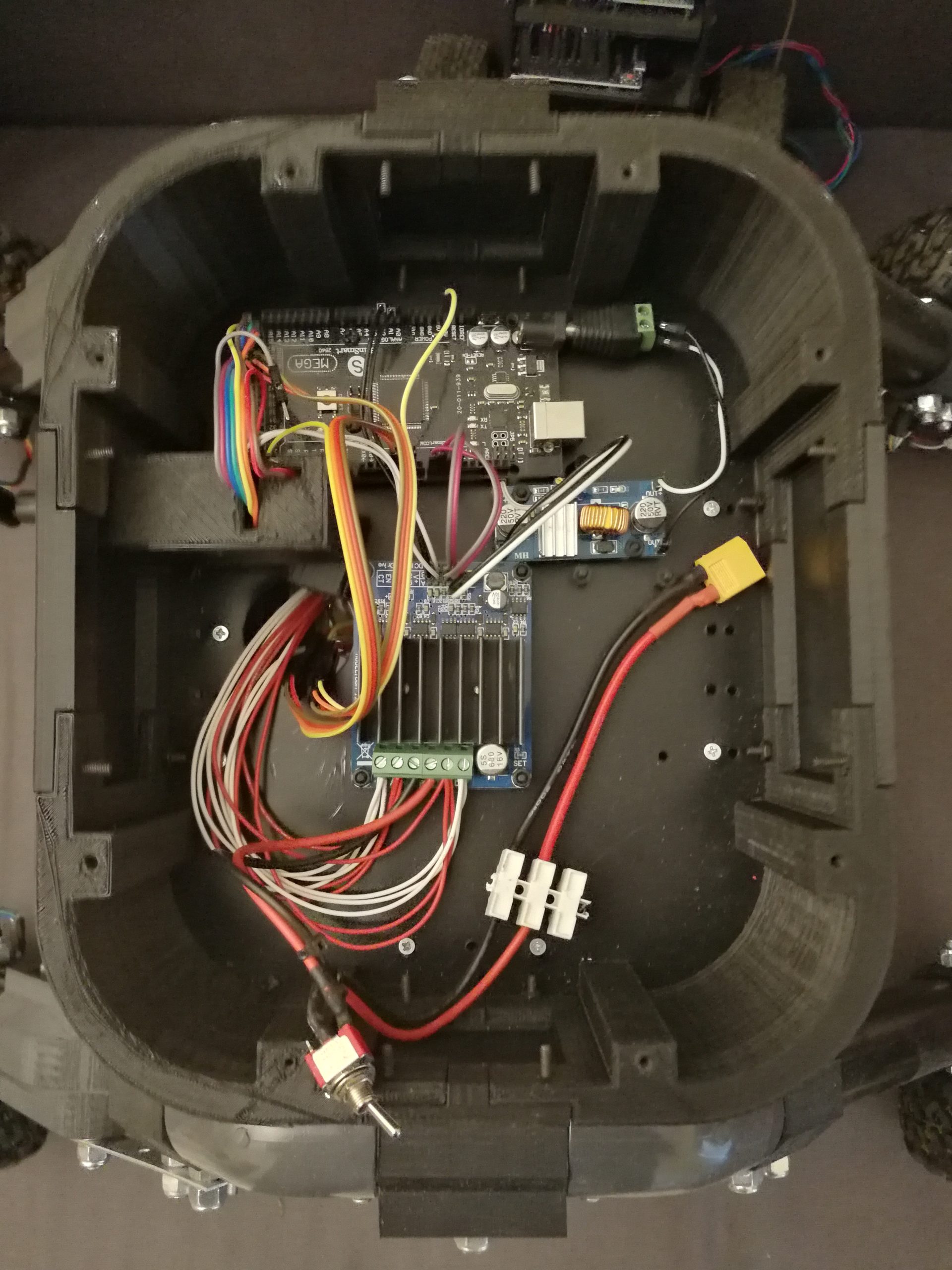
Phase 7 – Reviewing the Rocker Tubie firmware
Per consentire al Rocker Tubie di rispondere ai comandi impartiti con la Rocker Tubie Control Station, su quest’ultimo è installato un apposito microcontrollore (una scheda elettronica che è il vero cervello operativo del robot rover) dotato di un apposito programma, il firmware, che interpreta i comandi impartiti in linguaggio macchina (il linguaggio comprensibile dai microchip come quelli presenti sui microcontrollori Arduino), e quindi esegue calcoli, apre o chiude le porte (alle quali si accede anche attraverso i suoi pin), invia o riceve segnali singoli o in sequenza. Il firmware scritto con l’ambiente di sviluppo Arduino (anche detto IDE Arduino) ad esempio, viene solitamente scritto in C++, linguaggio informatico più comprensibile dagli umani, e una volta finita la programmazione il programma viene “compilato” in linguaggio macchina e trasferito sulla scheda Arduino attraverso un cavo (solitamente USB/Seriale) collegato tra il pc e il microcontrollore stesso.
I firmware necessari al funzionamento del Rocker Tubie e della sua stazione di controllo puoi trovarli nel Repository ufficiale del progetto Roker Tubie su GitHub, sono ambedue basati sul microcontrollore Arduino Mega 2560 R3, e sono resi disponibili con licenza open source GNU.
The Rocker Tubie Firmware
Il firmware “RockerTubie.ino” realizzato per il microcontrollore del Rocker Tubie include al suo interno una serie di librerie come:
The Rocker Tubie Firmware's libraries
Wire.h -> Libreria per il protocollo di comunicazione I2C
SPI.h -> Libreria per il protocollo di comunicazione per Interfaccia Seriale Periferica
RF24.h -> Libreria specifica per la comunicazione radio con chip NRF24L01
printf.h -> Libreria per stampare valori sul monitor seriale
DBH1.h -> Libreria per facilitare l’utilizzo del driver motori DBH
Come da schema dei collegamenti di seguito pubblichiamo un elenco riportante sul lato sinistro i pin dei moduli elettronici da collegare (Scheda di controllo motori DHB, Radio NRF24L01, LED Full Color 10 mm RGB) e sulla destra i pin del microcontrollore Arduino Mega 2560 R3 ai quali collegarli.
DBH motor driver – Arduino Mega 2560 R3 (pin connections)
ENA <– Pin 2 (Abilita motori lato Sinistro)
ENB <– Pin 4 (Abilita motori lato Destro)
IN1A <– Pin 3 (Input per motori A (lato SX) – deve essere un pin PWM)
IN1B <– Pin 5 (Input per motori B (lato DX) – deve essere un pin PWM)
IN2A <– Pin 6 (Input per motori A (lato SX) – deve essere un pin PWM)
IN2B <– Pin 9 (Input per motori B (lato DX) – deve essere un pin PWM)
CTA -> Pin 0 Analogico (Opzionale, riporta l’assorbimento istantaneo dei motori lato sinistro)
CTB -> Pin 1 Analogico (Opzionale, riporta l’assorbimento istantaneo dei motori lato destro)
NRF24L01 radio – Arduino Mega 2560 R3 (pin connections)
GND (Ground) -> Pin GND (terra, stabilisce il riferimento di tensione comune).
VCC (5V) <– Pin 5V (alimenta il modulo NRF24L01 con una tensione di 5 volt).
CE (Chip Enable) <– Pin 48 (abilita o disabilita il modulo NRF24L01 e ne controlla il funzionamento).
CSN (Chip Select Not) <– Pin 53 (seleziona il modulo NRF24L01 durante le operazioni di comunicazione. Quando è basso (LOW), il modulo è attivo e pronto per la comunicazione).
SCK (Serial Clock) <– Pin 52 (è parte dell’interfaccia SPI e viene utilizzato per sincronizzare i dati tra l’Arduino e il modulo NRF24L01).
MOSI (Master Out Slave In) <– Pin 51 (è parte dell’interfaccia SPI ed è utilizzato per inviare dati dall’Arduino al modulo NRF24L01).
MISO (Master In Slave Out) -> Pin 50 (è parte dell’interfaccia SPI ed è utilizzato per ricevere dati dal modulo NRF24L01 all’Arduino).
IRQ (Interrupt Request): In questo caso, non è collegato. L’IRQ è utilizzato per generare un’interruzione quando ci sono dati disponibili per la lettura o altri eventi speciali.
10mm full-color RGB LED – Arduino Mega 2560 R3 (pin connections)
Red <– Pin 44
Green <– Pin 45
Blue <– Pin 46
V <– 5V
Some details on the pins and their functions
I pin CTA e CTB sono pin della scheda di controllo motori che servono a riportare l’assorbimento istantaneo di quest’ultima al microcontrollore. La scheda di controllo motori genera su questi pin un voltaggio che corrisponde ad un valore analogico basato sull’assorbimento di corrente istantaneo.
ENA e ENB sono pin per abilitare l’uscita della scheda di controllo motori ai rispettivi motori del lato sinistro e lato destro del Rocker.
IN1A e IN2A così come IN1B e IN2B sono rispettivamente i pin di input per i motori A (lato sinistro) e B (lato destro).
When IN1A is set LOW and a PWM signal is supplied to IN2A, the motor will run in reverse.
When a PWM signal is supplied to IN1A and IN2A is driven LOW, the motor will run forward.
The driver requires a maximum duty cycle on the PWM input of no more than 98%.
A higher value could damage the driver or cause instability.
Using the DBH library:
The library for the DBH1 module, which I extended, is based on work by David Williams.
This library provides control of the motor driver module through the following types of commands:
The Rocker Tubie commands and their functions
Inizializza pin -> dbh.init(); (Questo comando inizializzerà i pin di default)
Avanti -> dbh.Forward(speedA, speedB);
Indietro -> dbh.Reverse(speedA, speedB);
Gira a destra -> dbh.TurnRight(speedA, speedB);
Gira a sinistra -> dbh.TurnLeft(speedA, speedB);
Frena -> dbh.Braking();
Folle -> dbh.Coasting();
Assorbimento Corrente -> dbh.GetCurrent();
Avanti solo Motori A (Sx) -> dbh.ForwardA(speedA);
Avanti solo Motori B (Dx) -> dbh.ForwardB(speedB);
Dietro solo Motori A (Sx) -> dbh.ReverseA(speedA);
Dietro solo Motori B (Dx) -> dbh.ReverseB(speedB);
Disabilita solo Motori A (Sx) -> dbh.DisableA();
Disabilita solo Motori B (Dx) -> dbh.DisableB();
Abilita solo Motori A (Sx) -> dbh.EnableA();
Abilita solo Motori B (Dx) -> dbh.EnableB();
Abilita Entrambi Motori A (Sx) e B (Dx) -> dbh.EnableBoth();
Disabilita Entrambi Motori A (Sx) e B (Dx) -> dbh.DisableBoth();
The NRF24L01 Radio Module
The modulo radio NRF24L01 per la comunicazione wireless utilizza il protocollo di comunicazione SPI (Serial Peripheral Interface) per interfacciarsi con l’Arduino Mega 2560 R3. Di seguito, spiego come i pin elencati sono collegati e quale ruolo svolgono nella comunicazione:
GND (Ground): Collegato al pin GND (terra) dell’Arduino Mega 2560 per stabilire il riferimento di tensione comune.
VCC (5V): Collegato al pin 5V dell’Arduino Mega 2560 per alimentare il modulo NRF24L01 con una tensione di 5 volt.
CE (Chip Enable): Collegato al pin 48 dell’Arduino Mega 2560. Questo pin è utilizzato per abilitare o disabilitare il modulo NRF24L01 e controllarne il funzionamento.
CSN (Chip Select Not): Collegato al pin 53 dell’Arduino Mega 2560. Questo pin è utilizzato per selezionare il modulo NRF24L01 durante le operazioni di comunicazione. Quando è basso (LOW), il modulo è attivo e pronto per la comunicazione.
SCK (Serial Clock): Collegato al pin 52 dell’Arduino Mega 2560. Questo pin è parte dell’interfaccia SPI e viene utilizzato per sincronizzare i dati tra l’Arduino e il modulo NRF24L01.
MOSI (Master Out Slave In): Collegato al pin 51 dell’Arduino Mega 2560. Questo pin è parte dell’interfaccia SPI ed è utilizzato per inviare dati dall’Arduino al modulo NRF24L01.
MISO (Master In Slave Out): Collegato al pin 50 dell’Arduino Mega 2560. Questo pin è parte dell’interfaccia SPI ed è utilizzato per ricevere dati dal modulo NRF24L01 all’Arduino.
IRQ (Interrupt Request): In questo caso, non è collegato. L’IRQ è utilizzato per generare un’interruzione quando ci sono dati disponibili per la lettura o altri eventi speciali.
In short, the hardware uses the SPI interface for communication between the Arduino Mega 2560 and the NRF24L01 module, letting them exchange data quickly and reliably.
Motor management
Speed control variables:
Nel codice, sono definite variabili come speedX, speedY, speedA, and speedB che sono utilizzate per gestire la velocità dei motori. Queste variabili rappresentano la velocità dei motori in due direzioni (X e Y) e due diversi motori (A e B).
Maximum and minimum speed:
Il firmware definisce anche le costanti maxSpeed e minSpeed che rappresentano la massima e la minima velocità impostabili per i motori. Questi valori possono essere utilizzati per garantire che i motori non superino determinati limiti di velocità.
Dead zone:
La variabile dz rappresenta la “DeadZone,” ovvero una zona in cui la lettura dei potenziometri dei joystick non è affidabile al 100%. La “DeadZone” è il punto in cui i movimenti sono considerati come “Stai fermo” e non vengono applicate velocità significative ai motori.
Calculating motor speeds:
Based on the data coming from the joysticks (read as XJoyReceived and YJoyReceived), the firmware calculates the motor speeds speedX and speedY. This calculation accounts for the "dead zone" and maps the joystick values to motor speeds within the set limits.
Motor commands:
After calculating the motor speeds, the firmware issues commands to the motors themselves. These commands can include forward, reverse, turn left or turn right, based on the calculated speeds.
Differential control:
The firmware also manages differential motor control when moving the robot forward or backward. This means the motors can spin at different speeds to make sure the robot moves in the desired direction.
In short, "motor management" in the firmware is responsible for reading the joystick data, calculating motor speeds from that data, applying speed limits, and then issuing commands to the robot's motors so it moves according to the joystick inputs. This is a crucial aspect of controlling and moving your Rocker Tubie robot.
Joystick control
"Joystick control" is an essential part of managing the Rocker Tubie robot's movement. Here is a more detailed explanation of how the firmware handles the joysticks:
Reading the joystick data:
I dati provenienti dai joystick collegati al robot vengono letti e memorizzati in diverse variabili, tra cui XJoyReceived, YJoyReceived, HJoyReceived, TJoyReceived, SJoyReceived, AJoyReceived, e BJoyReceived. Ogni variabile rappresenta un diverso input o stato dei joystick.
Mapping the joystick values:
After reading the joystick data, the firmware maps these values using the map() function. This mapping adapts the joystick values (which can range from 0 to 1023) to a specific range of motor speeds or other functions. For example, the joystick data can be mapped to a speed range from minSpeed to maxSpeed, where minSpeed and maxSpeed are constants defined in the code.
Calculating motor speeds:
After the mapping, the firmware calculates the motor speeds based on the joystick data. This calculation accounts for the joystick's X and Y directions and can vary depending on your specific motor configuration and control preferences.
Motor commands:
The calculated speeds are used to generate commands for the robot's motors. These commands can include moving forward, backward, turning left or turning right, depending on the calculated speeds and specific conditions.
Joystick buttons:
Besides the joystick positions, the firmware also reads the state of the joystick buttons. For example, buttons A and B are read. These inputs can be used to enable or disable specific robot features.
Using the joystick readings:
Once the joystick data has been read and processed, the firmware uses this information to drive the motors and control the robot's movement. The data can also be used for other actions or decisions within the firmware.
In short, "joystick control" in the firmware is responsible for reading and processing the data from the joysticks connected to the robot. This data is then used to calculate motor speeds, generate movement commands, and control other robot functions, allowing precise and intuitive control over its movement.
Managing and interpreting the LED light colors:
LED pins:
In the code, three pins are defined to control the LED lights: redPin, greenPin, and bluePin. Each pin is associated with a different LED color.
LED type (common anode or common cathode):
In the code, there is a commented-out declaration, #define COMMON_ANODE. This comment indicates the code is written to account for a possible LED type known as "common anode." In common-anode LEDs, the anode (long lead) connects to positive and the cathode (short lead) connects to negative. If you want to use LEDs with a "common cathode" configuration (where the cathode connects to positive), you would need to uncomment this line.
The setColor() function:
The setColor(int red, int green, int blue) function is responsible for setting the LED light colors. It takes three parameters — red, green, and blue — representing the brightness of the respective red, green and blue colors.
Controlling the LED light colors:
Depending on the data received or your robot's conditions, you can call the setColor() function to set the LED color to whatever you want it to represent. For example, in the code you can see calls to the setColor() function with specific values to set the LEDs to various colors such as red, blue, or green.
In short, "LED light management" in the firmware lets you control the color and brightness of the LED lights on board your Rocker Tubie robot. The 10mm RGB LED is a solid solution for visually indicating the robot's status or for other visual features you'd like to add to your own customization of the project.
Phase 8 – Functional testing and customizations
Procedure for the Rocker Tubie's functional tests
The functional tests will let you verify that your Rocker Tubie robot's main features — such as motor and LED control — work correctly using the supplied base firmware. Follow these steps to run the tests:
1. Power and connections
Make sure your Rocker Tubie robot is correctly connected to power and that all the wiring is secure.
2. Powering the NRF24L01 module
Check that the NRF24L01 module is correctly powered. This module should be connected to your Arduino Mega 2560 via the GND and VCC (5V) pins.
3. Checking the LED lights
Turn on the Rocker Tubie robot and watch how the LED lights behave. The firmware is designed to change the light color based on conditions or specific actions. For example, it might show red when the robot is stationary, blue when moving forward, and green when turning. Check that the LED lights respond correctly to the robot's actions.
4. Testing motor control
Use the joysticks to control the robot's movement. The code in the firmware manages the motor movements based on the joystick readings. Here's how you can run some tests:
Push the joystick forward to see if the robot moves forward.
Pull the joystick backward to check if the robot moves in reverse.
Move the joystick left or right to check the robot's lateral movement.
5. Testing the joystick buttons
If you've set up special functions for the joystick buttons in the firmware, press the joystick buttons (A and B) to check whether they affect the robot's behavior. For example, pressing a button might trigger a specific function or action, such as turning on the LED lights.
6. Adjusting the motor speeds
Watch how the motor speed changes as you move the joysticks further from or closer to the neutral position. Check that the motors respond smoothly to speed variations.
7. Differential control
If your robot supports differential control, run forward and backward movement tests while turning the joysticks to see how the robot responds and how the motor speeds vary.
8. Wrapping up the tests
After completing the tests, make an overall assessment of the robot's behavior. Check whether all the features seem to work as expected and whether the LED lights respond to commands.
These tests will help you verify that your Rocker Tubie robot works correctly with the supplied base firmware, letting you explore the motor control, LED light, and joystick button features.
9. Your customizations
One of the most interesting features of your Rocker Tubie is the ability to customize it to your liking. Here are some of the possible customizations:
Changing the LED light colors: The Rocker Tubie's firmware is designed to give you full control over the LED light colors. You can experiment with different color combinations or assign specific colors to certain robot actions or conditions. This is a great opportunity to give your robot a unique look.
Adjusting the motor speeds: The firmware code lets you adjust the motor speeds to your liking. You can increase or decrease the motors' maximum speed to match the kind of movement you want from your robot.
Customizing the joystick commands: If you're into electronics and programming, you can customize the joystick commands to perform specific actions or extra functions. This requires advanced programming knowledge, but gives you complete control over your robot's behavior.
Adding sensors: If you want to enhance your Rocker Tubie's capabilities, you can add sensors such as distance sensors, cameras, or other devices. These sensors can be integrated into the firmware code so the robot can respond intelligently to its surroundings.
If you ever need support, from the design stages through to the assembly and testing of your own Rocker Tubie, we're always here to advise and help you. Get in touch with us through Fanbotica's social networks or our other dedicated channels — experiment and have fun creating your own one-of-a-kind rover robot.
Salve, volevo chiederle quando saranno disponibili i kit del Rocker Tubie?
Gentile Lumitilla,
A breve saranno resi disponibili i kit Base e Combo della piattaforma Rocker Tubie, occorre pazientare ancora qualche giorno in quanto stiamo organizzando le forniture anche in vista della partecipazione del progetto al Maker Faire di Roma che si terrà dal 12 al 14 Ottobre. Appena saremo pronti pubblicheremo su tutti i nostri canali prezzi e disponibilità.
Ciao Francesco,
sono Francesco di San giorgio ci siamo conosciuti in fiera attendo ansioso la guida al tuo progetto specialmente la parte riguardante il controllo del rover con il joystik logitech grazie per avermi aperto un mondo a presto…
Buonasera Francy, siamo appena rientrati da Roma, domattina mi impegno a scrivere un post dettagliato esclusivamente dedicato alla stazione di controllo, un abbraccio e a domani.
Buongiorno Francesco, come promesso ho appena pubblicato un articolo con il progetto della stazione di controllo per Rocker Tubie, lo trovi a questo indirizzo: https://www.fanbotica.com/portfolio/stazione-di-controllo-per-rocker-tubie/
Fammi sapere come procede il tuo progetto, non esitare a chiedermi tutte le delucidazioni che ti occorrono.
A presto.
ciao ma il progetto è fermo?
sto realizzando un mio rover mi piacerebbe partire dalla base del tuo ottima la stazione di controllo, ma puoi caricare anche i collegamenti dell rocker? per favore
Buonasera Mirko, assolutamente no il progetto Rocker Tubie è attivo, come avrai certamente notato stiamo realizzando la nuova interfaccia grafica del sito Fanbotica, in home page troverai a breve (stimo un paio di giorni) tutti i progetti attivi, Rocker Tubie in primis, la timeline è quasi completa dunque troverai nei dettagli le fasi di montaggio della piattaforma, abbiamo realizzato una serie di tutorial esplicativi in merito. Scusaci per il disagio tecnico di questi giorni, chiedimi pure nel frattempo ogni dettaglio che ti occorre e te lo fornirò in tempi ancora più rapidi.
Buongiorno,
sarei interessato all’ acquisto del kit. Volevo chiedere se aggiornerete le restanti fasi di montaggio (dalla 5 in poi). Complimenti per il progetto.
Grazie
Ciao Ciro, i link ai kit per il Roker Tubie sono i seguenti:
1) Stazione di Controllo per Rocker Tubie Kit Base
2) Roker Tubie: Bare Bones Maker Kit, Master Maker Kit, Deluxe Maker Kit, Deluxe Complete Kit.
Inoltre puoi acquistare gli elementi facenti parte dei kit sia meccanici che elettronici nelle combinazioni e nei quantitativi che ti occorrono, per qualsiasi informazione a riguardo non esitare a contattarci su info@fanbotica.com.
Cercheremo di completare le ultime parti in tempo per la European Rover Challenge, ad ogni modo siamo sempre a disposizione dei maker per tutte le informazioni e la documentazione necessaria a supporto dei progetti, è la nostra filosofia condivisa. Benvenuto e Buon lavoro!