
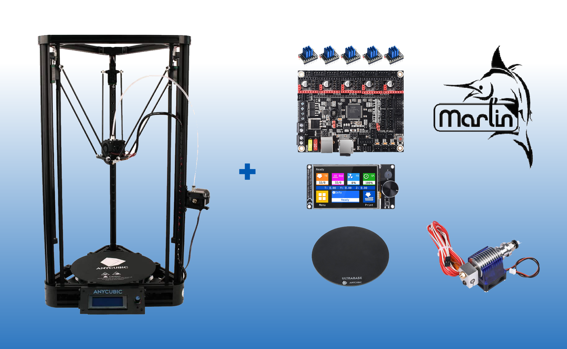
PURPOSE OF THIS GUIDE:
- Come aggiornare Delta Kossel Linear Plus with SKR 1.4 Turbo, driver Trinamic TMC2209, display Bigtreetech TFT35 V3.0, piatto Anycubic Ultrabase, firmware per motherboard Marlin 2.1.x Bugfix, firmware per display Bigtreetech TFT35 V3.0.27.x
LIVELLO DI DIFFICOLTÀ: medio
- La procedura per aggiornare Delta Kossel Linear Plus con SKR 1.4 Turbo richiede il disassemblaggio di diversi componenti della stampante: letto di stampa, scheda madre, display, e l’installazione dei nuovi componenti, è caldamente consigliato visionare più volte gli schemi tecnici dei componenti sia vecchi che nuovi contenuti in questa guida e forniti in dotazione con la tua stampante per evitare errori nei collegamenti dei cavi e dei pin.
- La maggiore difficoltà consisterà nel trovare i giusti valori per la propria stampante da impostare nel firmware per le funzioni “sensorless” StallGuard 2 dei driver TMC2209, in quanto ogni stampante necessita di valori appropriati da testare ed eventualmente modificare quindi non disponibili a priori.
TOPICS COVERED:
- Hardware and software installation and configuration
SOFTWARE COMPONENTS USED:
- Sistema operativo Windows 10 o analoghe distribuzioni, Visual Studio Code Versione 1.76.0 (user setup) con plugin Platformio.
PREREQUISITES:
- Stampante Anycubic Kossel Linear Plus assemblata a regola d’arte e già in grado di stampare oggetti 3D
- An Anycubic Probe 2 for Z-axis calibration and bed leveling
PHYSICAL DEVICES USED:
- A pc per programmare i firmware e compilarli, Anycubic Kossel Linear Plus, Bigtreetech SKR 1.4 Turbo, Bigtreetech TFT35 V3.0, piatto Anycubic Ultrabase, MicroSD per i trasferimenti dei firmware dal pc alla scheda madre e al display, Tester per la verifica dei contatti e per eventuali misurazioni elettroniche
- Consigliati: crimpatrice per terminali elettrici, crimpatrice per connettori tipo JST-XH da 2,5mm, kit di tali connettori femmina da 2, da 3 da 5 pin, pinze e tronchesina a becco piatto per taglio raso, set di giraviti a croce e punte esagonali.
GUIDE INTENDED FOR:

NOTES AND DISCLAIMER
- Any modification you carry out yourself is done entirely at your own risk and responsibility (the contents of this page are for educational purposes only);
- Any self-made modification to a device voids its warranty, approvals and quality certifications.
Revisione guida: 1.1
Abstract
Questo progetto spiega come ho fatto ad aggiornare la mia stampante 3D Delta Kossel Linear Plus with SKR 1.4 Turbo.
I wanted to carry out this project for three main reasons:
- Volevo ottenere una maggiore silenziosità della stampa adottando la tecnologia StealtChop 2 dei nuovi driver Trinamic TMC 2209,
- Ero desideroso di provare su una delta un processore a 32 bit per dotarla di maggiori risorse e capacità computazionali delle quali notoriamente questo tipo di stampanti sono voraci consumatrici quando eseguono in tempo reale i calcoli trigonometrici necessari a muovere i carrelli sui rispettivi assi X,Y,Z, e quindi a posizionare il terminale di stampa secondo le coordinate contenute nel file gcode in esecuzione,
- Volevo esplorare la possibilità di poter fare a meno dei finecorsa adottando la recentissima tecnologia Stallguard 2 di Trinamic,
Scopo di questa guida è illustrare una tecnica su come aggiornare una stampante delta Anycubic Kossel Linear Plus con una nuova scheda madre a 32 bit, ovvero la Bigtreetech SKR 1.4 Turbo 120Mhz, un display BTT TFT35 V3.0, e un piatto Anycubic Ultrabase.
Let's get started
- Preliminary notes
- Procedure
- Installing the SKR 1.4 Turbo motherboard
- Installing the Trinamic TMC2209 drivers
- Installing the BTT TFT35 V3.0 display
- Installing the Anycubic Ultrabase bed
- Installing the BTT Smart Filament Sensor V1.0
- Setting up the software environment
- Editing, compiling and uploading the Marlin V2.1.x Bugfix firmware
- Editing, compiling and uploading the BTT TFT35 V3.0 firmware
- Calibration and testing
Preliminary notes
Questo tipo di stampante 3D ha pianta triangolare (come la lettera maiuscola greca Δ) e piatto circolare, può avere diverse dimensioni a seconda del modello (Pulley o Linear, Linear Plus), nello specifico la mia Linear Plus ha dimensioni di stampa Φ240 mm x 270 mm e può raggiungere una temperatura all’hotend di 275°. Inoltre le stampanti “delta” possono essere dotate di carrelli di tipo Pulley (con piccole ruote gommate) o di guide lineari con cuscinetti a sfere, come nel mio caso.
Dal punto di vista della precisione nell’esecuzione delle stampe è preferibile la versione a guide lineari rispetto alla pulley. La tipologia a delta è prodotta attualmente in più versioni solitamente di dimensioni maggiori rispetto al modello Anycubic Kossel Linear Plus. The FLSUN produce il modello QQ con dimensioni di stampa Φ255 mm x 360 mm.
Differences between a delta printer and a Cartesian one
The layout of the X, Y, Z axes in delta printers
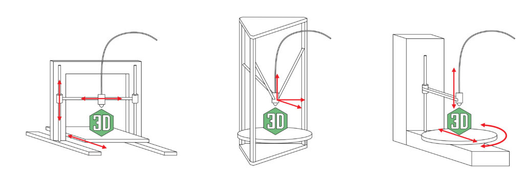
The main difference between a delta printer and a Cartesian one lies in how the X, Y and Z axes are used. On a delta, all three axes are vertical and interdependent, and each of the three carriages sliding vertically along them carries two carbon-fiber rods that support the hotend and hence the print nozzle, so that the combination of the three carriages' positions at set points along each axis determines the desired nozzle position relative to the printer's bed.
Nelle stampanti cartesiane al contrario ogni asse è indipendente dall’altro e un comando di spostamento di un carrello non interesserà gli altri. Nelle stampanti delta occorre che il processore della motherboard effettui complessi calcoli trigonometrici in tempo reale durante le fasi di stampa per movimentare i carrelli verticalmente su detti assi X,Y,Z ed ottenere il risultante spostamento della testa di stampa nei punti predeterminati dal file gcode dell’oggetto da stampare.
La motherboard (scheda madre) fornita di serie con la Anycubic Kossel Linear Plus is a Trigorilla basata su chip Arduino Mega 2560 a 8 bit. Sebbene non mi possa lamentare dei risultati ottenuti nel tempo con la Trigorilla, una motherboard con 32 bit è senz’altro più efficiente e veloce di una motherboard a 8 bit. Ecco uno dei motivi principali che mi ha spinto a sostituire la Trigorilla con una BigtreeTech SKR 1.4 Turbo, le cui specifiche, ulteriori caratteristiche e predisposizioni esporrò a breve. Qui di seguito gli schemi funzionali delle principali stampanti 3D, da sinistra a destra rispettivamente una cartesiana, una delta e una polare:
Endstops, or limit switches
Ma ritornando alle differenze tra una delta e una cartesiana, un’altra è sicuramente rappresentata da quei dispositivi atti a limitare il movimento dei carrelli entro un dato intervallo che in gergo tecnico si chiamano end-stop o finecorsa. Mentre le stampanti cartesiane sono predisposte per avere sia endstop Min that endstop Max, ovvero interruttori di finecorsa posti a limitare la corsa dei carrelli ad ambedue le estremità di ciascun asse, nelle delta sono presenti soltanto gli endstop Max nella parte terminale alta degli assi, mentre la funzione degli endstop Min è svolta nella maggioranza dei casi da una sonda predisposta per la calibrazione dell’asse Z, la Anycubic ne ha prodotte di due tipi auto leveling probe 1 e auto leveling probe 2, nel mio caso si tratta del più recente tipo 2. Qui uno schema dei collegamenti della scheda madre Trigorilla fornita di serie con la Anycubic Kossel Linear Plus:

The circular bed
Rispetto alle cartesiane che sono dotate di piatto quadrato le delta presentano un piatto circolare che può essere di varie dimensioni a seconda del modello, nel mio caso il piatto ha un diametro di Φ240mm. Il materiale nelle due tipologie di stampanti è pressocchè identico, vetro borosilicato (ovvero trattato per resistere ad alte temperature e in modo da avere una uniformità di superficie). Nella dotazione originale della mia Anycubic venne fornito anche un apposito adesivo da apporre sul piatto di vetro per facilitare il distacco dei pezzi, una volta ultimata la stampa.
Procedure
Installing the SKR 1.4 Turbo
After our brief overview of delta printers' features and the main differences from Cartesian ones, let's go through the upgrade steps in the right order, starting with replacing the Anycubic Trigorilla motherboard with the BigTreeTech SKR 1.4 Turbo, which has the following pinout:
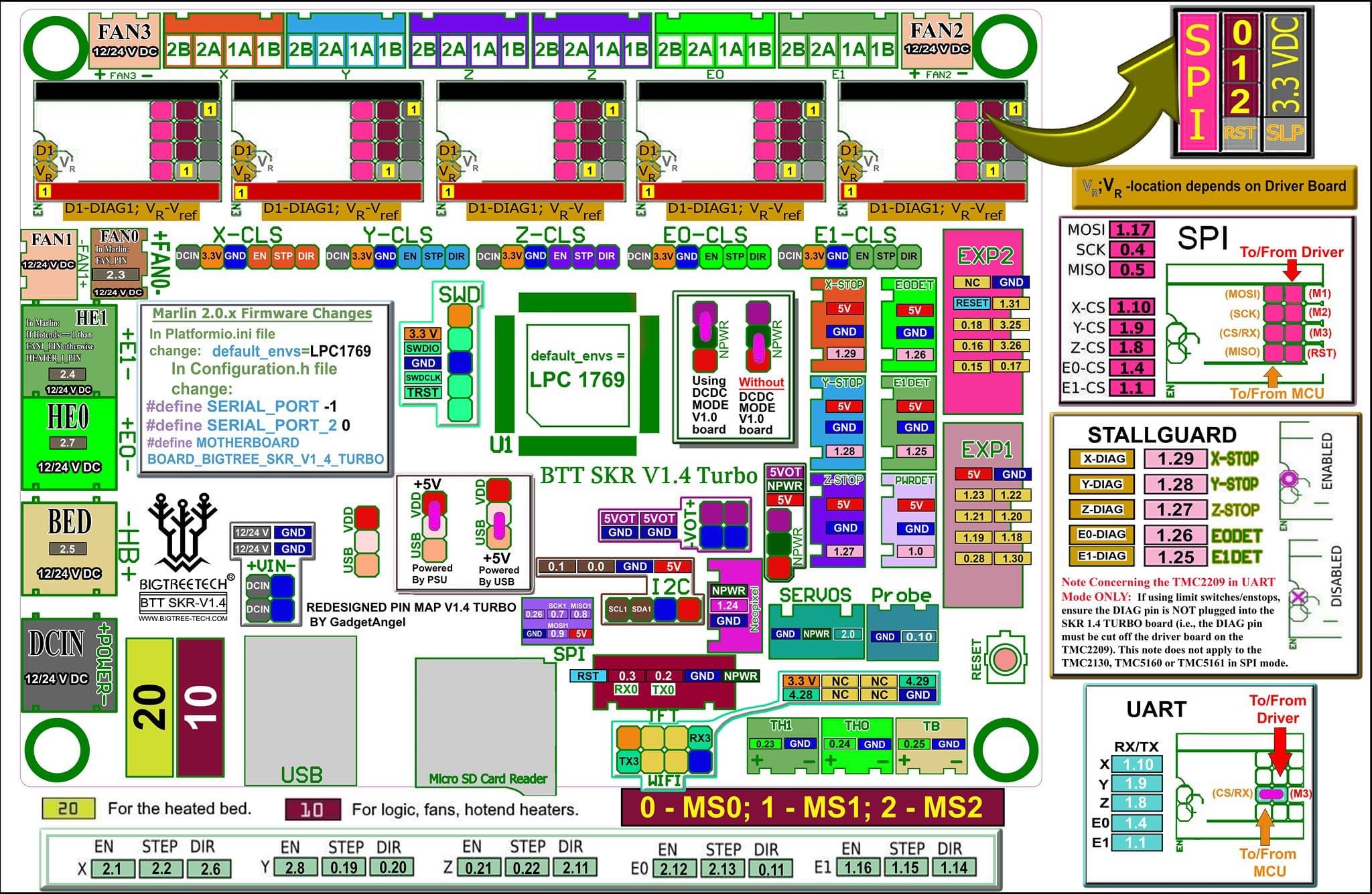

Tenendo presente lo schema sopra incominciamo col collegare i terminali rosso e nero provenienti dal piatto riscaldato (Hote Base) nel morsetto a vite nero denominato HB (il secondo cominciando a contare dall’angolo inferiore sinistro dell’immagine qui sopra), facendo bene attenzione a rispettare la polarità, cavo rosso in basso e cavo nero in alto. Guardate e ricontrollate sempre le serigrafie sul lato posteriore della scheda per essere sicuri di non aver invertito i poli.
Ora procedete con i 2 cavi rossi provenienti dall’hot-end 0, non dovrebbero avere alcuna polarità dunque fermateli nelle due posizioni previste dal morsetto HE0,
Proseguite collegando i terminali delle 2 ventoline presenti sull’Hot End, quella che serve a raffreddarlo potete collegarla nella posizione a sinistra FAN, mentre l’altra a controllo numerico per il raffreddamento della stampa nella posizione indicata da CNC FAN (in questo modello l’unica posizione a controllo numerico).
Ora è la volta dei terminali dei termistori due provenienti dall’Hot-End che collocherete nella posizione in basso a destra indicata con TH0 e due provenienti dal piatto riscaldato che collocherete a destra di questa nella posizione TB, non ci sono polarità da rispettare. Per una connessione più salda anzicchè lasciare i connettori di tipo Dupont potreste decidere di sostituirli crimpando dei connettori a 2 posizioni del tipo JST-XH da 2,5mm.
La sonda Anycubic Probe 2 va connessa al terminale indicato dalla sigla PWR DET come successivamente specificheremo anche nel codice del firmware.
I 3 cavi del display EXP 1, EXP 2 e TFT vanno collegati nelle rispettive posizioni contrassegnate nell’area LCD e TFT della scheda. Per il cavo TFT tenete presente il giusto orientamento e quindi la corrispondenza con le serigrafie riportate nel retro della scheda, ogni collegamento sulla scheda deve corrispondere a quello del display. Anche qui per una connessione più salda anzicchè lasciare il connettore di tipo Dupont potreste decidere di sostituirlo crimpando nel verso giusto un connettore a 5 posizioni del tipo JST-XH da 2,5mm.
Since the SKR 1.4 Turbo motherboard is mounted outside the printer, you'll need 4 one-meter cables for the X, Y, Z and E0 stepper motors — the stock ones will be too short; you can buy replacements here. Again, for a sturdier connection, it's better to use 4-position 2.5mm JST-XH cables.
I cavi X,Y,Z, e E0 vanno collocati rispettivamente nelle posizioni indicate da XM, YM, ZAM, and E0M, facendo attenzione a rispettare la corrispondenza delle posizioni dei fili di ciascun terminale che sono 2B, 2A, 1A, 1B, basta che teniate presente la posizione dei fili e l’ordine dei colori sulla vecchia scheda madre Trigorilla e sui cavi che utilizzate, sono identici alla SKR 1.4 / SKR 1.4 Turbo.
Before connecting the last cables — the power ones — we need to install the Trinamic TMC2209 drivers.
Installing the Trinamic TMC2209 drivers

BigTreeTech, la società dietro l’elettronica SKR, sviluppa anche i propri driver che montano il chip TMC2209. Si distinguono molto facilmente poiché, come nel driver precedente, il nome e la versione sono stampati sulla parte superiore della targhetta.
If that's your case, setting them up for UART mode couldn't be simpler. First, pull out all the jumpers on your board and leave only the ones in the MS3 position in place, as you can see in the image below (SKR V1.4):

Con questa semplice modifica dovrebbe essere sufficiente avere una modalità UART intelligente e StallGuard™ e potremo utilizzare motori X e Y senza finecorsa.
According to the manufacturer's documentation, if you only want smart UART mode and plan to keep using mechanical limit switches for the X, Y, Z motors, they recommend cutting a pin on the driver, as shown in the image below.
Since cutting it seems a bit drastic to me personally, you can instead choose to carefully bend it over or solder it flat to one side. That way, if you ever want to change the configuration later and use sensorless mode (without mechanical limit switches), you'll be able to do so without any trouble.
Installing the BTT TFT35 V3.0 display
Per utilizzare la doppia modalità di funzionamento modalità MARLIN (modalità testo) e modalità TOUCHSCREEN (touch screen) del display Beegtreetech TFT35 V3.0, dovremo effettuare 3 collegamenti tra il retro del display e la nostra motherboard SKR 1.4 Turbo, che sono quelli che puoi vedere nell’immagine seguente, ovvero le 2 tipiche connessioni seriali 12864, che sono i connettori LCD-EXP1 e LCD-EXP2, e il connettore TouchScreen che SKR utilizzerà per comunicare con il display, contrassegnato come TFT nell’immagine. In merito a quest’ultimo fai bene attenzione alla nomenclatura dei pin indicati dalla serigrafia della scheda (+5V, GND, RX, TX, RST), il nome di ciascun pin deve corrispondere a quello del pin ad esso collegato sulla SKR 1.4 Turbo.


The last thing to do before connecting the power cables to the SKR 1.4 Turbo is to set the board's power-mode jumper (5V USB or 12/24V VDD). If you plan to power the board from a USB cable, choose the USB option; if you're using a 12V or 24V power supply, choose the VDD option.
Finally, connect the black and red power cables respectively into the bottom and top channels of the DC-IN input, on the left-hand side of the SKR 1.4 Turbo image above — mind the polarity, or you'll fry the board and everything connected to it.
Installing the Anycubic Ultrabase bed
Una evoluzione del semplice piatto in vetro borosilicato liscio è rappresentata dal piatto Anycubic Ultrabase, che non necessita di alcun adesivo avendo la superficie trattata appositamente con un materiale a pattern puntiforme che permette il facile distacco dei pezzi una volta raffreddato il piatto, di contro per fare aderire le stampe occorre riscaldarlo ad una temperatura di almeno 50°C.
As with Cartesian printers, the bed may or may not be heated, depending on whether there's an additional aluminum plate containing a heating element, which of course needs to be connected to the motherboard using two silicone-insulated wires, black and red. We'll go into whether a heated bed is needed, specifically, depending on the various materials used for 3D printing.

Setting up the software environment
Installing Visual Studio
Prima di iniziare a modificare Marlin, ti consiglio di installare un buon editor di codice. Tra i più usati c’è Visual Studio Code. Non solo è un potente editor di codice, ma ha anche un gran numero di estensioni e puoi persino compilare Marlin direttamente da esso.
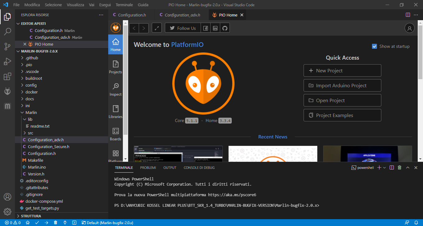
Visual Studio Code può essere scaricato gratuitamente (è completamente gratuito) dal sito Web ufficiale. E una volta che hai modificato Marlin e i parametri necessari – che troverai un po’ più avanti – puoi compilarlo e caricare il tuo nuovo firmware sulla stampante.
Installing the PlatformIO IDE extension
Una volta installato correttamente Visual Studio Code, eseguiremo il programma e cercheremo nella barra laterale di sinistra un’icona con una specie di Puzzle (come puoi vedere nell’immagine sopra)
Con questo accederemo alla sezione in cui vengono amministrate le estensioni . Lì andremo alla casella di ricerca, inseriremo il nome “PlatformIO IDE” e attenderemo che appaia nell’elenco. Quindi lo selezioneremo e premeremo il pulsante “Installa” per iniziare il processo di installazione.
Il tempo di installazione dipenderà dal tuo computer e dal sistema operativo che hai. Ci vorrà un po’ di tempo, quindi sii paziente e aspetta che finisca completamente. Una volta terminato, il software stesso ti avviserà con un messaggio nella parte in basso a destra “PlatformIO IDE è stato installato con successo! Si prega di ricaricare la finestra”.
Nel caso in cui non sia installato Python, Visual Studio Code ti chiederà di installarlo, poiché è completamente necessario per questa estensione. Dovresti vedere un messaggio come questo “PlatformIO: Impossibile trovare Python 2.7 o 3.5+ Interpreter funzionante. Si prega di installare l’ultimo Python 3 e riavviare VSCode”. E ti offrirà la possibilità di scaricarlo premendo un pulsante, fare clic su di esso, scaricare il software e installarlo.
Downloading the Marlin bugfix-2.1.x firmware and the Configurations folder
The next step, of course, is to download the Marlin firmware source onto your computer. To do this, go to its official website and open the download section.
Qui il link diretto. Di solito scarico il firmware nella versione bug fixes, appena sotto la scritta “Download” . Lì, fai clic sul collegamento bugfix-2.1.x.zip , che è quello disponibile oggi per la versione bugfix-2.1.x
Keep in mind, though, that new updates and revisions are released regularly. So by the time you're reading this article there might be a newer version with a different name. That's not a big deal — just download the latest version and you're set.
Scaricato il firmware generale, ora scarichiamo il set di cartelle con le configurazioni per ogni tipo di stampante 3D, per farlo basta cliccare su “View/Download” sotto “Configurations”, si aprirà la pagina github corrispondente, facciamo clic su “Code” e poi dal menu che si apre su “Dowload ZIP”.
Ora decomprimiamo in sequenza sia il firmware generale Marlin-bugfix-2.1.x.zip that Configurations-bugfix-2.1.x.zip in una cartella che chiameremo “Delta_Upgrade”.
Spostiamoci nella cartella “Kossel Linear Plus”, che dovrebbe essere a questo punto nella locazione:
“Delta_Upgrade\Configurations-bugfix-2.1.x\config\examples\delta\Anycubic\Kossel Linear Plus”,
copiamo i files Configuration.h e Configuration_adv.h nella cartella “Marlin”:
“Delta_Upgrade\Marlin-bugfix-2.1.x\Marlin”, sovrascrivendo i due files esistenti.
Step 06: Editing, compiling and uploading the Marlin V2.1.x Bugfix firmware
In this section I'll explain how to configure the SKR v1.4 / SKR v1.4 Turbo electronics to make the most of what the (sensorless) TMC2209 drivers have to offer, and how to best configure the "hybrid" BTT TFT35 v3.0 display as well.
Editing the "Platformio.ini" file
Se lo hai chiuso, riapri Visual Studio Code. Clicca su “File” in alto a sinistra, poi su “Apri Cartella”, ora seleziona la cartella “Marlin-bugfix-2.1.x”. Il primo file che andremo a modificare è il “Platformio.ini” per indicare al nostro compilatore che tipo di microprocessore abbiamo a bordo della nostra elettronica. Se non lo indichiamo con precisione, Visual Studio Code avrebbe problemi a compilare il nostro firmware. Trovi questo file nel menu a sinistra, se non visualizzi un elenco di files clicca sulla prima icona in alto a sinistra.
Questo file si trova all’interno del firmware Marlin, esattamente nella directory principale. Qui hai i valori trai quali sceglierai quello relativo alla tua scheda BigtreeTech SKR, Versione 1.4 (con processore LPC1768) oppure Versione 1.4 Turbo (con processore LPC1769):
| Board type | ENV_DEFAULT |
| SKR v1.4 | LPC1768 |
| SKR v1.4 Turbo | LPC1769 |
Conoscendo la scheda che utilizzeremo, modificheremo “Platformio.ini” e nel campo “env_default” metteremo il valore corrispondente alla nostra elettronica. Nel mio caso ho la SKR v1.4 Turbo quindi ho modificato il campo inserendo il valore “LPC1769”.
[platformio]
src_dir = Marlin
boards_dir = buildroot/share/PlatformIO/boards
default_envs = LPC1769
include_dir = Marlin
Editing the "Configuration.h" file
Once we've set our electronics' processor type in Visual Studio Code, let's move on to editing the two files that need changing in Marlin.
Inizieremo aprendo con Visual Studio Code il file “Configuration.h” e andando a definire se la nostra è una stampante Anycubic Kossel Plus o Pulley, solo se ci troviamo nel primo caso (vedi caratteristiche di entrambi i modelli nei paragrafi precedenti) occorrerà decommentare la riga “#define ANYCUBIC_KOSSEL_PLUS” in questo modo:
/**
* Choose your version:
*/
// normal size or plus?
#define ANYCUBIC_KOSSEL_PLUS
Now let's configure the Anycubic Probe type for automatic bed leveling. If your Anycubic Probe looks like the one in the following image, it's model 2 — otherwise it will be model 1:
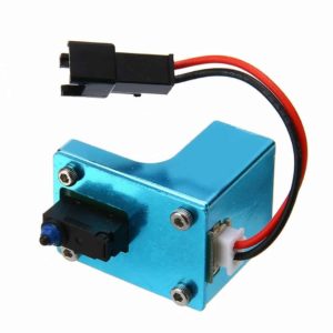
If you have a multimeter, you can easily check this. Probe 2 is NC — normally closed — meaning it's normally "on," so you'll read a very low resistance, or you can get a continuity beep across the contacts.
// Anycubic Probe version 1 or 2 see README.md; 0 for no probe
#define ANYCUBIC_PROBE_VERSION 2
Make sure you've chosen the correct bed type.
If you want to change it, simply switch:
#define ANYCUBIC_KOSSEL_ENABLE_BED 2 to:
- No heated bed:
#define ANYCUBIC_KOSSEL_ENABLE_BED 0 - Standard heated bed with a black sticker:
#define ANYCUBIC_KOSSEL_ENABLE_BED 1 - Ultrabase_BED_bed_KOSSELABLE_BED 2
// Heated Bed:
// 0 ... no heated bed
// 1 ... aluminium heated bed with "BuildTak-like" sticker
// 2 ... ultrabase heated bed
#define ANYCUBIC_KOSSEL_ENABLE_BED 2
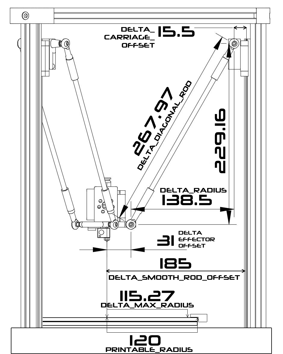
In this section we need to set our delta printer's correct dimensional parameters, so that printed objects come out correct and accurate.
The Kossel Linear Plus has a heated bed with an outer diameter of 230mm.
Ultrabase beds for the Kossel come in two outer diameters: 200mm and 240mm.
In my case I have a standard 240mm heated bed with a 240mm Ultrabase mounted on it, which means my printable radius is: (240mm − unreachable margin (usually 10mm)) / 2 = 115mm.
The code contains various printer-specific definitions and parameters, such as the maximum build size, the maximum radius reachable by the delta arms, the distance between the print surface and the nozzle's "home" position, and so on.
The first part of the code contains an "if" condition that checks whether the printer in use is an Anycubic Kossel Linear Plus model. If it is, the firmware sets that printer's specific parameters. In particular, the corresponding values are defined for the following variables:
“PRINTABLE_RADIUS” (raggio massimo di stampa, ovvero il diametro del piatto di stampa diviso due),
“DELTA_MAX_RADIUS” (raggio massimo raggiungibile dai bracci della stampante delta al netto dell’ingombro dei fermi del piatto),
“DELTA_DIAGONAL_ROD” (la distanza tra i fori degli snodi dei bracci diagonali),
“DELTA_SMOOTH_ROD_OFFSET” (la distanza tra il centro dell’effettore e il centro delle sferette dei carrelli sulle guide lineari),
“DELTA_EFFECTOR_OFFSET” (la distanza orizzontale tra il centro degli snodi inferiori delle aste di supporto e il centro della piastra effettore),
“DELTA_CARRIAGE_OFFSET” (la distanza orizzontale tra il centro degli snodi superiori delle aste di supporto e il centro delle sferette dei carrelli sulle guide lineari).
The second part of the code runs if the printer isn't an Anycubic Kossel Linear Plus, and sets the parameters specific to whatever model is in use. In particular, it defines the maximum print radius via the "PRINTABLE_RADIUS" variable, the maximum radius reachable by the delta arms via "DELTA_MAX_RADIUS," the distance between the diagonal rods' holes via "DELTA_DIAGONAL_ROD," and the horizontal distance between the center of the smooth rod and the center of the effector plate via "DELTA_RADIUS."
In entrambe le parti del codice, sono presenti altre variabili utilizzate per calibrare la stampante delta, come la variabile “DELTA_HEIGHT” che definisce la distanza tra il piano di stampa e la posizione di “home” del nozzle e la variabile “DELTA_TOWER_ANGLE_TRIM” che consente di regolare la precisione dei bracci delta.
Overall, this configuration code is an important tool for customizing the Marlin 2.1 bugfix firmware for your own 3D printer. It's important to understand the various parameters and variables in the code in order to optimize your printer's performance and produce high-quality printed objects.
If you're not sure of your printer's measurements, find the correct length of your rods by removing them and measuring them axis by axis with a sliding tape measure, using the center of the holes as reference points, and correct the value accordingly:
#if ENABLED(ANYCUBIC_KOSSEL_PLUS)
// Print surface diameter/2 minus unreachable space (avoid collisions with vertical towers).
#define PRINTABLE_RADIUS 115.27 // (mm)
// Maximum reachable area
#define DELTA_MAX_RADIUS 105.0 // (mm)
// Center-to-center distance of the holes in the diagonal push rods.
#define DELTA_DIAGONAL_ROD 268 // (mm)
// Horizontal offset from middle of printer to smooth rod center.
#define DELTA_SMOOTH_ROD_OFFSET 185 // (mm)
// Horizontal offset of the universal joints on the end effector.
#define DELTA_EFFECTOR_OFFSET 31 // (mm)
// Horizontal offset of the universal joints on the carriages.
#define DELTA_CARRIAGE_OFFSET 15.5 // (mm)
// Horizontal distance bridged by diagonal push rods when effector is centered.
#define DELTA_RADIUS (DELTA_SMOOTH_ROD_OFFSET-(DELTA_EFFECTOR_OFFSET)-(DELTA_CARRIAGE_OFFSET)) // (mm) Get this value from G33 auto calibrate
#else
// Print surface diameter/2 minus unreachable space (avoid collisions with vertical towers).
#define PRINTABLE_RADIUS 90.0 // (mm)
// Maximum reachable area
#define DELTA_MAX_RADIUS 90.0 // (mm)
// Center-to-center distance of the holes in the diagonal push rods.
#define DELTA_DIAGONAL_ROD 218.0 // (mm)
// Horizontal distance bridged by diagonal push rods when effector is centered.
#define DELTA_RADIUS 97.0 // (mm) Get this value from G33 auto calibrate
#endif

// Distance between bed and nozzle Z home position
#define DELTA_HEIGHT 282.19 // (mm) Get this value from G33 auto calibrate

#define DELTA_ENDSTOP_ADJ { 0.0, 0.0, 0.0 } // Get these values from G33 auto calibrate

// Trim adjustments for individual towers
// tower angle corrections for X and Y tower / rotate XYZ so Z tower angle = 0
// measured in degrees anticlockwise looking from above the printer
#define DELTA_TOWER_ANGLE_TRIM { 0.0, 0.0, 0.0 } // Get these values from G33 auto calibrate

// Delta radius and diagonal rod adjustments (mm)
//#define DELTA_RADIUS_TRIM_TOWER { 0.0, 0.0, 0.0 }
//#define DELTA_DIAGONAL_ROD_TRIM_TOWER { 0.0, 0.0, 0.0 }

#endif
The following variable moves the print head down by about 50mm after homing, at the end of a print session.
#define DELTA_HOME_TO_SAFE_ZONE (Se hai intenzione di stampare modelli alti, commenta questa riga.)
 // After homing move down to a height where XY movement is unconstrained
#define DELTA_HOME_TO_SAFE_ZONE
A standard Kossel without corner braces, with well-tensioned belts, can manage about 60mm/s max.
If you do have corner braces, on the other hand, you can easily reach 100mm/s and even higher speeds.
/**
* Default Max Feed Rate (mm/s)
* Override with M203
* X, Y, Z [, I [, J [, K]]], E0 [, E1[, E2...]]
*/
#define DEFAULT_MAX_FEEDRATE { 100, 100, 100, 100}
The maximum acceleration values can be set in this part of the configuration file.
Keep in mind that if you try to print with a higher acceleration than this, the firmware won't let you.
I consider these values a "failsafe" against acceleration values that are too high.
/**
* Default Max Acceleration (change/s) change = mm/s
* (Maximum start speed for accelerated moves)
* Override with M201
* X, Y, Z [, I [, J [, K]]], E0 [, E1[, E2...]]
*/
#define DEFAULT_MAX_ACCELERATION { 3000, 3000, 3000, 3000 }
This one is almost critical.
If you're using different firmware, check whether this line is defined.
It ensures that after a restart, the printer will still use the delta calibration values.
/**
* Normally G28 leaves leveling disabled on completion. Enable one of
* these options to restore the prior leveling state or to always enable
* leveling immediately after G28.
*/
#define RESTORE_LEVELING_AFTER_G28
//#define ENABLE_LEVELING_AFTER_G28
The homing speed is a crucial setting. It lets you slow down homing, making both homing and calibration more accurate.
Instead of homing fast and "slamming" into the limit switches, you can approach them slowly and trigger them gently.
// Homing speeds (mm/min)
// Delta only homes to Z
#define HOMING_FEEDRATE_MM_M { (40*60), (40*60), (40*60) }
Edit the parameters to configure the communication ports (primary and secondary) and the communication speed. For this last one I usually set 250,000 baud, but if you run into problems, use 115,200 baud instead.
/**
 * Select the serial port on the board to use for communication with the host.
 * This allows the connection of wireless adapters (for instance) to non-default port pins.
 * Serial port -1 is the USB emulated serial port, if available.
 * Note: The first serial port (-1 or 0) will always be used by the Arduino bootloader.
 *
 * :[-1, 0, 1, 2, 3, 4, 5, 6, 7]
 */
#define SERIAL_PORT 0

/**
 * Serial Port Baud Rate
 * This is the default communication speed for all serial ports.
 * Set the baud rate defaults for additional serial ports below.
 *
 * 250000 works in most cases, but you might try a lower speed if
 * you commonly experience drop-outs during host printing.
 * You may try up to 1000000 to speed up SD file transfer.
 *
 * :[2400, 9600, 19200, 38400, 57600, 115200, 250000, 500000, 1000000]
 */
#define BAUDRATE 250000
//#define BAUD_RATE_GCODE     // Enable G-code M575 to set the baud rate

/**
 * Select a secondary serial port on the board to use for communication with the host.
 * Currently Ethernet (-2) is only supported on Teensy 4.1 boards.
 * :[-2, -1, 0, 1, 2, 3, 4, 5, 6, 7]
 */
#define SERIAL_PORT_2 -1
//#define BAUDRATE_2 250000   // Enable to override BAUDRATE
Now we'll tell Marlin exactly what type of board our printer has. Here's a list of the different SKR models and, next to each, the parameter you need to enter:
| Board type | Parameter |
| SKR v1.1 | BOARD_BTT_SKR_V1_1 |
| SKR v1.3 | BOARD_BTT_SKR_V1_3 |
| SKR v1.4 | BOARD_BTT_SKR_V1_4 |
| SKR v1.4 Turbo | BOARD_BTT_SKR_V1_4_TURBO |
Nel mio caso si tratta di una Bigtreetech SKR V1.4 TURBO, quindi lo indico a Marlin come segue:
// Choose the name from boards.h that matches your setup
#ifndef MOTHERBOARD
#define MOTHERBOARD BOARD_BTT_SKR_V1_4_TURBO
#endif
Next we'll set the driver type we have and the motors they're fitted to. Look for the following lines related to the X, Y, Z axis drivers and the E0 extruder, and change the default values to TMC2209; if your drivers aren't Trinamic TMC2209, change the corresponding entries to match what you have. Leave every axis and extruder you won't be using commented out.
#define X_DRIVER_TYPE TMC2209
#define Y_DRIVER_TYPE TMC2209
#define Z_DRIVER_TYPE TMC2209
//#define X2_DRIVER_TYPE A4988
//#define Y2_DRIVER_TYPE A4988
//#define Z2_DRIVER_TYPE A4988
//#define Z3_DRIVER_TYPE A4988
//#define Z4_DRIVER_TYPE A4988
//#define I_DRIVER_TYPE A4988
//#define J_DRIVER_TYPE A4988
//#define K_DRIVER_TYPE A4988
#define E0_DRIVER_TYPE TMC2209
//#define E1_DRIVER_TYPE A4988
//#define E2_DRIVER_TYPE A4988
//#define E3_DRIVER_TYPE A4988
//#define E4_DRIVER_TYPE A4988
//#define E5_DRIVER_TYPE A4988
//#define E6_DRIVER_TYPE A4988
//#define E7_DRIVER_TYPE A4988
Still editing the "Configuration.h" file, we'll change two other very important parameters we mustn't forget. The first will help us enable Marlin emulation on our display.
Ciò significa che se si utilizza un “display ibrido” as the Bigtreetech TFT35 V3.0, è possibile passare dalla modalità TouchMode (testo e grafica) alla modalità Marlin (solo testo) premendo il pulsante principale per 3 secondi. È una soluzione che accontenta sia gli amanti del touch che degli encoder rotativi.
// RepRapDiscount FULL GRAPHIC Smart Controller
// https://reprap.org/wiki/RepRapDiscount_Full_Graphic_Smart_Controller
//
#define REPRAP_DISCOUNT_FULL_GRAPHIC_SMART_CONTROLLER
Il secondo parametro ci permetterà di supportare la memorizzazione della Eeprom sulla nostra stampante , è indispensabile attivarla.
/**
* EEPROM
*
* Persistent storage to preserve configurable settings across reboots.
*
* M500 - Store settings to EEPROM.
* M501 - Read settings from EEPROM. (i.e., Throw away unsaved changes)
* M502 - Revert settings to "factory" defaults. (Follow with M500 to init the EEPROM.)
*/
#define EEPROM_SETTINGS // Persistent storage with M500 and M501
//#define DISABLE_M503 // Saves ~2700 bytes of PROGMEM. Disable for release!
#define EEPROM_CHITCHAT // Give feedback on EEPROM commands. Disable to save PROGMEM.
#define EEPROM_BOOT_SILENT // Keep M503 quiet and only give errors during first load
#if ENABLED(EEPROM_SETTINGS)
//#define EEPROM_AUTO_INIT // Init EEPROM automatically on any errors.
#endif
Editing the "Configuration_adv.h" file
È il turno del file “Configuration_adv.h”. Questo file contiene le configurazioni più avanzate del firmware Marlin, oltre a quelle più sperimentali o in sviluppo.
Il primo parametro che dobbiamo modificare è l’interpolazione dei passi del nostro driver. In questo modo, consentiremo al driver TMC2209 di eseguire le interpolazioni automaticamente. Verifica che accanto ad “INTERPOLATE” ci sia il valore “true”:
/**
* Interpolate microsteps to 256
* Override for each driver with driver_INTERPOLATE settings below
*/
#define INTERPOLATE true
Quindi indicheremo i valori della tensione (650 per assi X,Y,Z e 750 per estrusore E0) e i micro passi a cui deve funzionare ciascuno dei motori. Ho solo X, Y, Z ed E0, quindi modificherò i valori nella sezione corrispondente:
#if AXIS_IS_TMC(X)
#define X_CURRENT 650 // (mA) RMS current. Multiply by 1.414 for peak current.
#define X_CURRENT_HOME X_CURRENT // (mA) RMS current for sensorless homing
#define X_MICROSTEPS 16 // 0..256
#define X_RSENSE 0.11
#define X_CHAIN_POS -1 // -1..0: Not chained. 1: MCU MOSI connected. 2: Next in chain, ...
//#define X_INTERPOLATE true // Enable to override 'INTERPOLATE' for the X axis
#endif

#if AXIS_IS_TMC(X2)
#define X2_CURRENT 800
#define X2_CURRENT_HOME X2_CURRENT
#define X2_MICROSTEPS X_MICROSTEPS
#define X2_RSENSE 0.11
#define X2_CHAIN_POS -1
//#define X2_INTERPOLATE true
#endif

#if AXIS_IS_TMC(Y)
#define Y_CURRENT 650
#define Y_CURRENT_HOME Y_CURRENT
#define Y_MICROSTEPS 16
#define Y_RSENSE 0.11
#define Y_CHAIN_POS -1
//#define Y_INTERPOLATE true
#endif

#if AXIS_IS_TMC(Y2)
#define Y2_CURRENT 800
#define Y2_CURRENT_HOME Y2_CURRENT
#define Y2_MICROSTEPS Y_MICROSTEPS
#define Y2_RSENSE 0.11
#define Y2_CHAIN_POS -1
//#define Y2_INTERPOLATE true
#endif

#if AXIS_IS_TMC(Z)
#define Z_CURRENT 650
#define Z_CURRENT_HOME Z_CURRENT
#define Z_MICROSTEPS 16
#define Z_RSENSE 0.11
#define Z_CHAIN_POS -1
//#define Z_INTERPOLATE true
#endif

#if AXIS_IS_TMC(Z2)
#define Z2_CURRENT 800
#define Z2_CURRENT_HOME Z2_CURRENT
#define Z2_MICROSTEPS Z_MICROSTEPS
#define Z2_RSENSE 0.11
#define Z2_CHAIN_POS -1
//#define Z2_INTERPOLATE true
#endif

#if AXIS_IS_TMC(Z3)
#define Z3_CURRENT 800
#define Z3_CURRENT_HOME Z3_CURRENT
#define Z3_MICROSTEPS Z_MICROSTEPS
#define Z3_RSENSE 0.11
#define Z3_CHAIN_POS -1
//#define Z3_INTERPOLATE true
#endif

#if AXIS_IS_TMC(Z4)
#define Z4_CURRENT 800
#define Z4_CURRENT_HOME Z4_CURRENT
#define Z4_MICROSTEPS Z_MICROSTEPS
#define Z4_RSENSE 0.11
#define Z4_CHAIN_POS -1
//#define Z4_INTERPOLATE true
#endif

#if AXIS_IS_TMC(I)
#define I_CURRENT 800
#define I_CURRENT_HOME I_CURRENT
#define I_MICROSTEPS 16
#define I_RSENSE 0.11
#define I_CHAIN_POS -1
//#define I_INTERPOLATE true
#endif

#if AXIS_IS_TMC(J)
#define J_CURRENT 800
#define J_CURRENT_HOME J_CURRENT
#define J_MICROSTEPS 16
#define J_RSENSE 0.11
#define J_CHAIN_POS -1
//#define J_INTERPOLATE true
#endif

#if AXIS_IS_TMC(K)
#define K_CURRENT 800
#define K_CURRENT_HOME K_CURRENT
#define K_MICROSTEPS 16
#define K_RSENSE 0.11
#define K_CHAIN_POS -1
//#define K_INTERPOLATE true
#endif

#if AXIS_IS_TMC(E0)
#define E0_CURRENT 750
#define E0_MICROSTEPS 16
#define E0_RSENSE 0.11
#define E0_CHAIN_POS -1
//#define E0_INTERPOLATE true
#endif

#if AXIS_IS_TMC(E1)
#define E1_CURRENT 800
#define E1_MICROSTEPS E0_MICROSTEPS
#define E1_RSENSE 0.11
#define E1_CHAIN_POS -1
//#define E1_INTERPOLATE true
#endif

#if AXIS_IS_TMC(E2)
#define E2_CURRENT 800
#define E2_MICROSTEPS E0_MICROSTEPS
#define E2_RSENSE 0.11
#define E2_CHAIN_POS -1
//#define E2_INTERPOLATE true
#endif

#if AXIS_IS_TMC(E3)
#define E3_CURRENT 800
#define E3_MICROSTEPS E0_MICROSTEPS
#define E3_RSENSE 0.11
#define E3_CHAIN_POS -1
//#define E3_INTERPOLATE true
#endif

#if AXIS_IS_TMC(E4)
#define E4_CURRENT 800
#define E4_MICROSTEPS E0_MICROSTEPS
#define E4_RSENSE 0.11
#define E4_CHAIN_POS -1
//#define E4_INTERPOLATE true
#endif

#if AXIS_IS_TMC(E5)
#define E5_CURRENT 800
#define E5_MICROSTEPS E0_MICROSTEPS
#define E5_RSENSE 0.11
#define E5_CHAIN_POS -1
//#define E5_INTERPOLATE true
#endif

#if AXIS_IS_TMC(E6)
#define E6_CURRENT 800
#define E6_MICROSTEPS E0_MICROSTEPS
#define E6_RSENSE 0.11
#define E6_CHAIN_POS -1
//#define E6_INTERPOLATE true
#endif

#if AXIS_IS_TMC(E7)
#define E7_CURRENT 800
#define E7_MICROSTEPS E0_MICROSTEPS
#define E7_RSENSE 0.11
#define E7_CHAIN_POS -1
//#define E7_INTERPOLATE true
#endif
Now we'll tell Marlin what voltage our power supply provides — the most common are 12V or 24V. In my case it's 24V, so I tell Marlin as follows:
 #define CHOPPER_TIMING CHOPPER_DEFAULT_12V // All axes (override below)
//#define CHOPPER_TIMING_X CHOPPER_TIMING // For X Axes (override below)
//#define CHOPPER_TIMING_X2 CHOPPER_TIMING_X
Let's enable, among other things, various temperature protections Trinamic offers for our TMC2209 drivers:
/**
* Monitor Trinamic drivers
* for error conditions like overtemperature and short to ground.
* To manage over-temp Marlin can decrease the driver current until the error condition clears.
* Other detected conditions can be used to stop the current print.
* Relevant G-codes:
* M906 - Set or get motor current in milliamps using axis codes X, Y, Z, E. Report values if no axis codes given.
* M911 - Report stepper driver overtemperature pre-warn condition.
* M912 - Clear stepper driver overtemperature pre-warn condition flag.
* M122 - Report driver parameters (Requires TMC_DEBUG)
*/
#define MONITOR_DRIVER_STATUS
Procediamo ad attivare l’opzione StallGuard™ nel nostro firmware Marlin. StallGuard™ è una tecnologia brevettata da Trinamic che consente di effettuare misurazioni del carico sui nostri motori passo-passo.
E ti starai chiedendo, a cosa serve questa tecnologia? Ebbene la risposta è semplice. StallGuard™ è in grado di rilevare con precisione gli arresti del motore e quindi può eliminare l’uso di qualsiasi tipo di finecorsa.
Dunque quello che faremo è eliminare i finecorsa degli assi X,Y,Z. Devi semplicemente decommentare l’opzione SENSORLESS_HOMING e sarà disponibile.
Puoi anche configurare la sensibilità con i parametri X_STALL_SENSITIVITY e Y_STALL_SENSITIVITY . Il valore 0 significa che non si fermerà e il valore 255 indica che il minimo ostacolo disabilita il movimento del motore. Un valore consigliato per iniziare i test è 75, da affinare con prove e riprove naturalmente:
/**
* Use StallGuard to home / probe X, Y, Z.
*
* TMC2130, TMC2160, TMC2209, TMC2660, TMC5130, and TMC5160 only
* Connect the stepper driver's DIAG1 pin to the X/Y endstop pin.
* X, Y, and Z homing will always be done in spreadCycle mode.
*
* X/Y/Z_STALL_SENSITIVITY is the default stall threshold.
* Use M914 X Y Z to set the stall threshold at runtime:
*
* Sensitivity TMC2209 Others
* HIGHEST 255 -64 (Too sensitive => False positive)
* LOWEST 0 63 (Too insensitive => No trigger)
*
* It is recommended to set HOMING_BUMP_MM to { 0, 0, 0 }.
*
* SPI_ENDSTOPS *** Beta feature! *** TMC2130/TMC5160 Only ***
* Poll the driver through SPI to determine load when homing.
* Removes the need for a wire from DIAG1 to an endstop pin.
*
* IMPROVE_HOMING_RELIABILITY tunes acceleration and jerk when
* homing and adds a guard period for endstop triggering.
*
* Comment *_STALL_SENSITIVITY to disable sensorless homing for that axis.
*/
#define SENSORLESS_HOMING // StallGuard capable drivers only

#if EITHER(SENSORLESS_HOMING, SENSORLESS_PROBING)
// TMC2209: 0...255. TMC2130: -64...63
#define X_STALL_SENSITIVITY 98
#define X2_STALL_SENSITIVITY X_STALL_SENSITIVITY
#define Y_STALL_SENSITIVITY 98
#define Y2_STALL_SENSITIVITY Y_STALL_SENSITIVITY
#define Z_STALL_SENSITIVITY 98
//#define Z2_STALL_SENSITIVITY Z_STALL_SENSITIVITY
//#define Z3_STALL_SENSITIVITY Z_STALL_SENSITIVITY
//#define Z4_STALL_SENSITIVITY Z_STALL_SENSITIVITY
//#define I_STALL_SENSITIVITY 8
//#define J_STALL_SENSITIVITY 8
//#define K_STALL_SENSITIVITY 8
//#define SPI_ENDSTOPS // TMC2130 only
#define IMPROVE_HOMING_RELIABILITY
#endif
With this parameter we'll get a cleaner signal for our Trinamic TMC2209 drivers. It's recommended to enable it, so we'll do it like this:
/**
* Beta feature!
* Create a 50/50 square wave step pulse optimal for stepper drivers.
*/
#define SQUARE_WAVE_STEPPING
E infine, attiveremo questa opzione, che ci darà la possibilità di eseguire il debug e conoscere in tempo reale lo stato dei nostri driver. È abbastanza utile sapere se abbiamo configurato tutto correttamente e se abbiamo attivato correttamente la modalità UART.
/**
* Enable M122 debugging command for TMC stepper drivers.
* M122 S0/1 will enable continuous reporting.
*/
#define TMC_DEBUG
Installing the BTT Smart Filament Sensor V1.0
Se sei appassionato di stampa 3D, probabilmente hai già sentito parlare di un dispositivo chiamato “filament sensor”. Ma cos’è esattamente un filament sensor e a cosa serve?
In breve, un filament sensor è un dispositivo che rileva la presenza e l’avanzamento del filamento di plastica all’interno della stampante 3D. Il sensore di filamento è un’aggiunta molto utile alla tua stampante 3D, poiché ti consente di monitorare in modo preciso la quantità di filamento presente sulla bobina e di evitare che la stampante continui a stampare quando il filamento è terminato.
Uno dei sensori di filamento più diffusi sul mercato è il BigTreeTech Smart Filament Sensor V1.0. Questo sensore è compatibile con molte stampanti 3D e può essere facilmente installato. Una volta installato, il sensore di filamento monitora costantemente l’avanzamento del filamento e segnala alla stampante quando il filamento è finito.
The BigTreeTech Smart Filament Sensor V1.0 è dotato della capacità di rilevare la rottura del filamento, quando questa viene rilevata interrompe immediatamente la stampa e segnala il problema al software di controllo e quindi all’utente.
In sintesi, il BigTreeTech Smart Filament Sensor V1.0 è uno strumento molto utile per tutti gli appassionati di stampa 3D. Grazie alla sua capacità di monitorare costantemente l’avanzamento del filamento, il sensore di filamento può aiutare a prevenire problemi durante la stampa e conseguentemente ad evitare di sprecare tempo e materiale.
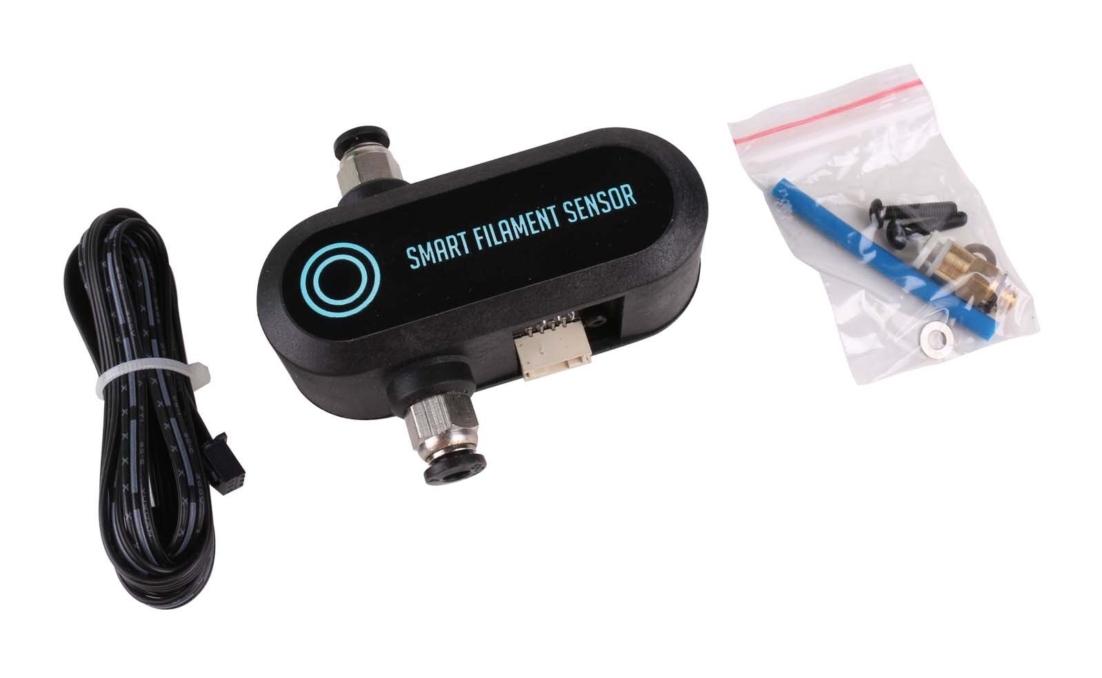
Connecting the BTT SFS V1.0 sensor to the BigTreeTech SKR 1.4 TURBO
In generale, è consigliabile collegare il sensore di filamento direttamente alla scheda madre, poiché ciò consentirà di utilizzare le funzionalità di rilevamento del firmware Marlin.
Nel tuo caso, dal momento che stai utilizzando la scheda madre BigTreeTech SRK 1.4 TURBO, puoi utilizzare uno dei connettori del sensore di filamento presenti sulla scheda madre. In particolare, il connettore “E0-DET” (Extruder 0 Filament Detection) dovrebbe essere quello corretto per il tuo sensore.
il connettore “E0-DET” ha 3 pin che sono dall’alto in basso: 5V, GND, P1.26 e si trova sulla parte anteriore destra della scheda madre BigTreeTech SRK 1.4 TURBO, tra i connettori X-STOP e EXP2 (vedi schema BTT SKR 1.4 TURBO precedente).
Questo connettore è definito alla riga #define FIL_RUNOUT_PIN P1_26 // E0DET nel file del firmware dedicato alla definizione dei pins della scheda, ovvero pins_BTT_SKR_V1_4.h.
Configuring the Marlin firmware to enable the BTT Smart Filament Sensor V1.0's features
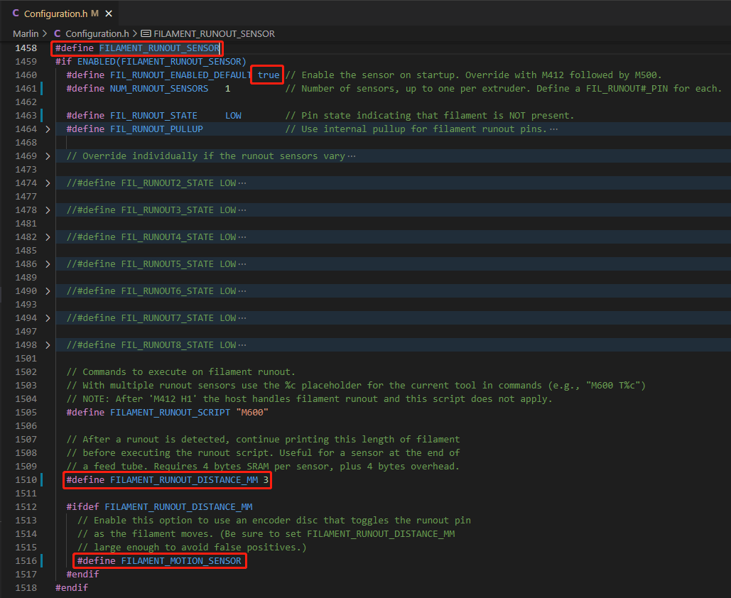
Uncomment the following lines (by removing the double slash):
#define FILAMENT_RUNOUT_SENSOR,
#define FILAMENT_RUNOUT_DISTANCE_MM 7 e impostarlo su 7 mm (la precisione di rilevamento di SFS V1.0 è 7 mm),
#define FILAMENT_MOTION_SENSOR,
#define NOZZLE_PARK_FEATURE,
#define ADVANCED_PAUSE_FEATURE e impostare parametri specifici in base alla propria stampante.
It's recommended to connect the SFS V1.0 to the motherboard rather than the touchscreen; in that case, the Marlin configuration is as described above.
The config.ini file del touch screen in questo caso non deve essere modificato per lo scopo.
Quando l’SFS V1.0 invece è collegato al Touch Screen, va commentata la riga #define FILAMENT_RUNOUT_SENSOR in Marlin per disabilitare il rilevamento di Marlin e decommentata #define M114_DETAIL per il Touch Screen, di converso va abilito il rilevamento del Touch Screen nel config.ini file, impostato fil_runout:1 per abilitare il rilevamento e fil_runout_distance:7 per la precisione.
Editing, compiling and uploading the BTT TFT35 V3.0 firmware
Configuration
La configurazione del firmware può essere modificata modificando il file config.ini(or the config_rrf.inifile rinominato) utilizzando un semplice editor di testo (assicurarsi di utilizzare la codifica UTF).
You can upload a configuration without needing to re-upload the firmware or the TFT folder, as long as the firmware and the configuration file are the same version.
Editing the configuration file
NOTA: gli utenti del firmware RepRap devono apportare le modifiche utilizzando il config_rrf.inifile modello e rinominandolo in config.ini.
Per modificare il config.ini file, seguire le istruzioni qui: Detailed instructions.
Installation
NOTA: per i dispositivi con supporto per unità flash USB, è possibile aggiornare le icone , i caratteri , la configurazione e i file della lingua da un’unità flash USB nello stesso modo in cui si esegue tramite una scheda SD. Tuttavia, il firmware può essere aggiornato solo utilizzando una scheda SD.
The following steps are needed to install the firmware:
Copia il firmware BIGTREE_TFT*_V*.*.*.bin precompilato o il tuo firmware autocompilato, più la cartella del tuo tema preferito insieme alla radice di una scheda SD vuota non superiore a 8 GB e formattata come FAT32: TFT*config.ini

Facoltativamente, copiare uno o più language_*.inifile sulla scheda SD. In questo modo potrai passare dall’inglese alla/e lingua/e caricata/e dal menu Lingua presente nel firmware del TFT. Si consiglia di caricare il numero minimo di lingue per mantenere basso l’utilizzo della memoria. Il language_*.inifile può essere modificato per cambiare il testo mostrato sul TFT:

Posizionare la scheda SD con BIGTREE_TFT*_V*.*.*.bin, the TFT*cartella config.inie i file facoltativi language_*.ininel lettore di schede SD del TFT e reimpostare il TFT (o, facoltativamente, spegnere e riaccendere la stampante) per avviare il processo di aggiornamento:
Update process shown on the TFT screen:
A successful update looks like this on the screen:

… e il nome degli elementi sulla scheda SD cambia in questo:

If one or more parts of the update fail, an error message will be shown. Follow the on-screen information to update the missing or outdated items:

Once the update is finished and the files have been renamed, you can reuse them again. To do this, rename the item(s) back to what they were called before the update and start the update process again.
After a successful update, the TFT will move to one of the following menus:
-
- Menu principale : l’aggiornamento è completato ed è possibile utilizzare il TFT
- Menu di calibrazione touch screen : è necessario un processo di post-installazione prima di passare al menu principale. Consultare la sezione Post-installation to complete the post-installation process
SUGGERIMENTO: Formattare la scheda SD dopo l’aggiornamento del firmware nel caso in cui si desideri stampare da essa.
Marlin dependencies
Minimum Marlin firmware version: 2.1.1
Release date: 2022-09-22
Firmware source: https://github.com/MarlinFirmware/Marlin/releases
To use all the features and functionality supported by the TFT, the following options need to be enabled in the Marlin firmware.
General options that MUST always be enabled:
EEPROM_SETTINGS (in Configuration.h)
BABYSTEPPING (in Configuration_adv.h)
AUTO_REPORT_TEMPERATURES (in Configuration_adv.h
AUTO_REPORT_POSITION (in Configuration_adv.h)
EXTENDED_CAPABILITIES_REPORT (in Configuration_adv.h)
M115_GEOMETRY_REPORT (in Configuration_adv.h)
M114_DETAIL (in Configuration_adv.h)
REPORT_FAN_CHANGE (in Configuration_adv.h)
Options to support printing from onboard media:
SDSUPPORT (in Configurazione.h)
LONG_FILENAME_HOST_SUPPORT (in Configurazione_adv.h)
AUTO_REPORT_SD_STATUS (in Configurazione_adv.h)
SDCARD_CONNECTION_ONBOARD (in Configurazione_adv.h)
Options to support host dialogs:
EMERGENCY_PARSER (in Configurazione_adv.h)
SERIAL_FLOAT_PRECISION 4 (in Configurazione_adv.h)
HOST_ACTION_COMMANDS (in Configurazione_adv.h)
HOST_PROMPT_SUPPORT (in Configurazione_adv.h)
HOST_STATUS_NOTIFICATIONS (in Configurazione_adv.h)
Options to support M73 with the host:
Options to support host communication (as a prerequisite)
SET_PROGRESS_MANUALLY (in Configuration_adv.h)
M73_REPORT (in Configuration_adv.h)
Options to support M600 with the host and the load/unload menu:
Options to support host communication (as a prerequisite)
NOZZLE_PARK_FEATURE (in Configuration.h)
ADVANCED_PAUSE_FEATURE (in Configuration_adv.h)
PARK_HEAD_ON_PAUSE (in Configuration_adv.h)
FILAMENT_LOAD_UNLOAD_GCODES (in Configuration_adv.h)
Options to fully support the Bed Leveling menu:
Z_MIN_PROBE_REPEATABILITY_TEST (in Configurazione.h)
G26_MESH_VALIDATION (in Configurazione.h)
Z_STEPPER_AUTO_ALIGN (in Configurazione_adv.h)
Post-installation
If significant changes were made by the installed firmware, a post-installation process is automatically started, consisting of touchscreen calibration.
See the section Touch screen calibration to complete the process.
Updating the configuration
See the section Configuration per la configurazione config.inidel file.
NOTES:
- Per i dispositivi con supporto per unità flash USB, è possibile aggiornare le icone , i caratteri , la configurazione e i file di lingua da un’unità flash USB nello stesso modo in cui si esegue tramite una scheda SD. Tuttavia, il firmware può essere aggiornato solo utilizzando una scheda SD
- La seguente procedura può essere applicata anche a qualsiasi combinazione di risorse (es. solo icone , icone + caratteri , file di configurazione + lingua ecc.)
To update the firmware's configuration:
- Copia il file modificato
config.ininella root della scheda SD. La capacità della scheda SD deve essere inferiore o uguale a 8 GB e formattata come FAT32 - Insert the SD card into the TFT's SD card slot and press the TFT's reset button (or power the printer off and back on)
- The TFT's configuration will be updated from the configuration file on restart
- The
config.inifile verrà rinominatoconfig.ini.CURdopo l’aggiornamento della configurazione
Touchscreen calibration
The touchscreen calibration process begins by showing a white screen with a red dot in the top-right corner and the following text:
Touch Screen Calibration - Please click on the red dot
Once the process has started, to calibrate the touchscreen tap (with your finger or a stylus):
- the red dot in the top-left corner
- then the red dot in the top-right corner
- then the red dot in the bottom-right corner
- and finally the black dot in the center of the screen to finish the calibration
Repeat the process if the following message is shown:
Adjustment failed, please try again.
Forcing touchscreen calibration
Touchscreen calibration can be forced in two ways:
- da menu: La calibrazione può essere avviata dal menu Menu->Impostazioni->Schermo-> Regolazione TSC
- from a hard reset: calibration starts once the hard reset process finishes
Full reset
NOTES:
- The hard reset process is usually used as a last resort when the firmware isn't working properly (e.g. in case of freezes, on-screen errors, etc.)
- A meno che le impostazioni codificate predefinite non siano state configurate correttamente (ad esempio, è stato installato un firmware autocompilato), dopo un hard reset il TFT in genere deve essere riconfigurato con il
config.inifile appropriato.
The hard reset process consists of:
- resetting the TFT's configuration to the TFT's hardcoded default settings
- avviare il processo di calibrazione del touch screen all’avvio prima di passare al menu principale
To fully reset the firmware:
- Crea un file vuoto denominato
reset.txt - Copia il
reset.txtfile nella root della scheda SD. La capacità della scheda SD deve essere inferiore o uguale a 8 GB e formattata come FAT32 - Insert the SD card into the TFT's SD card slot and press the TFT's reset button (or power the printer off and back on)
- The TFT's configuration will be reset to the TFT's hardcoded default settings, and the touchscreen calibration process will start on restart
- The
reset.txtfile verrà rinominatoreset.txt.DONEdopo il completamento del processo di calibrazione del touch screen
Restoring the default settings
When the hardcoded default settings are correctly configured for a TFT and its basic functions, such as menu navigation, work fine, in case of problems the user can choose to apply just a configuration reset (soft reset) instead of a hard reset.
To restore the default settings:
- Accedere a Menu->Impostazioni-> menu Funzioni
- Selezionare e premere sulla voce Ripristina impostazioni predefinite
- Premere il pulsante Ok per confermare il ripristino
- Exit the menu
Customization
Boot screen and icons
See the section Customization guides for detailed information.
firmware
View the full instructions
SUGGERIMENTO: In caso di problemi durante la compilazione del firmware TFT, provare a riavviare VSC. Se questo non aiuta e stai utilizzando macOS, elimina le cartelle dei pacchetti e delle piattaforme solitamente presenti sotto la cartella /Users/***username***/.platformio/.
Vertical screen orientation – Portrait mode
All precompiled firmware available in the Copy to SD Card root directory to updatecartella sono compilati per supportare l’orientamento dello schermo standard (orizzontale).
If the TFT needs to be mounted in a vertical orientation (e.g. rotated 90°), the firmware needs to be compiled with portrait-mode support and installed following this procedure:
- Launch VSCode
- Aprire
platformio.ini - Rimuovere il commento (rimuovere il
;carattere iniziale) dalla seguente riga:
; -DPORTRAIT_MODE="_portrait" ; uncomment here to enable Portrait Mode .bin firmware generation - Compile the firmware
- Viene creato il file binario nominato
BIGTREE_TFT*_V*.*.*.x_portrait.bin(vedi la presenza del suffisso _portrait ) - Rinominare il file binario con il nome standard
BIGTREE_TFT*_V*.*.*.x.bin - Copia
BIGTREE_TFT*_V*.*.*.x.bin, theTFT*cartellaconfig.iniand alsoreset.txt(necessario per forzare la calibrazione dello schermo) nella scheda SD - Proceed with the firmware update (following the usual procedure)
Troubleshooting
Calibration and testing
It's likely that after compiling the Marlin firmware and uploading it to your electronics, an EEPROM error may show up on your touchscreen or on the Marlin emulation screen. If that's the case, don't worry — it's normal.
You need to run these g-code commands one at a time (don't enter them all at once) and the problem will be solved. The commands are M502, M500 and M501, in that order. Here's a description of what each one does.
M502 – Fully restores factory settings. Doesn't require the EEPROM_SETTINGS parameter.
M500 – Saves the entire current configuration to our EEPROM.
M501 – Loads the current values from the EEPROM.
Another problem that usually comes up when using touchscreen mode is that it shows no communication with our printer. This happens because we have different communication speeds selected in our Marlin firmware and on our display.
If you've followed this manual to the letter, you'll remember we set communication to 250,000 baud in Marlin (#define BAUDRATE 250000). Now you need to find where communication is configured on the display and set that same value there.
Remember you need to do this from "Touch mode," not from the Marlin emulation (text mode). To make it easier, here's the path to follow:
MENU -> CONFIGURA -> VELOCITÀ UART
veramente esaustivo, fatto molto bene ottimo.
io ho come hardware una scheda della bigtretech v1.4 turbo con dei drivers tmc5160.
L’esempio proposto da voi è applicabile anche ai miei drivers?
in attesa di una vostra risposta porgo i miei distinti saluti.
Giovanni
Grazie Giovanni per i complimenti, siamo felici che la guida le sia stata utile!
La risposta breve è sì, la guida è in gran parte applicabile, ma i driver TMC5160 presentano alcune differenze importanti rispetto ai TMC2209 dell’esempio che richiedono adattamenti specifici. Ecco cosa cambia e cosa rimane uguale:
Cosa rimane identico
Poiché la sua scheda madre è la stessa SKR 1.4 Turbo della guida, queste sezioni non cambiano affatto:
platformio.ini: default_envs = LPC1769 — invariato
Configuration.h: #define MOTHERBOARD BOARD_BTT_SKR_V1_4_TURBO — invariato
Tutte le impostazioni dimensionali della stampante delta, gli endstop, il display TFT35 V3.0, l’EEPROM, la porta seriale — invariati
1. Jumper sulla scheda: modalità SPI (non UART)
Questa è la differenza hardware più importante. I TMC5160 comunicano tramite il protocollo SPI, non UART come i TMC2209. Sulla SKR 1.4 Turbo occorre quindi inserire tutti e tre i jumper (MS1, MS2, MS3) su ogni slot driver, al contrario di quanto indicato nella guida per i TMC2209 (dove si lasciava solo MS3). Non è inoltre necessario piegare o tagliare alcun pin del driver.
2. Configuration.h — Tipo di driver
Sostituisca TMC2209 con TMC5160 per tutti gli assi utilizzati:
#define X_DRIVER_TYPE TMC5160
#define Y_DRIVER_TYPE TMC5160
#define Z_DRIVER_TYPE TMC5160
//#define X2_DRIVER_TYPE A4988
//#define Y2_DRIVER_TYPE A4988
//#define Z2_DRIVER_TYPE A4988
//#define Z3_DRIVER_TYPE A4988
//#define Z4_DRIVER_TYPE A4988
#define E0_DRIVER_TYPE TMC5160
//#define E1_DRIVER_TYPE A4988
…
3. Configuration_adv.h — Resistenza di senso (RSENSE)
Il valore RSENSE dei TMC5160 è diverso da quello dei TMC2209 (0.11). Il valore corretto dipende dalla versione del suo driver BTT:
BTT TMC5160 V1.2/V1.3: #define X_RSENSE 0.075
BTT TMC5160 Pro: #define X_RSENSE 0.022
Verifichi la versione stampata sul suo driver e applichi il valore corretto a tutti gli assi (X, Y, Z, E0). Usare un valore errato comprometterebbe il controllo della corrente sui motori.
#if AXIS_IS_TMC(X)
#define X_CURRENT 800 // (mA) RMS — da adattare ai suoi motori
#define X_CURRENT_HOME X_CURRENT
#define X_MICROSTEPS 16
#define X_RSENSE 0.075 // 0.022 se ha la versione Pro
#define X_CHAIN_POS -1
#endif
#if AXIS_IS_TMC(Y)
#define Y_CURRENT 800
#define Y_CURRENT_HOME Y_CURRENT
#define Y_MICROSTEPS 16
#define Y_RSENSE 0.075
#define Y_CHAIN_POS -1
#endif
#if AXIS_IS_TMC(Z)
#define Z_CURRENT 800
#define Z_CURRENT_HOME Z_CURRENT
#define Z_MICROSTEPS 16
#define Z_RSENSE 0.075
#define Z_CHAIN_POS -1
#endif
#if AXIS_IS_TMC(E0)
#define E0_CURRENT 900
#define E0_MICROSTEPS 16
#define E0_RSENSE 0.075
#define E0_CHAIN_POS -1
#endif
4. Configuration_adv.h — Sensibilità StallGuard (SENSORLESS_HOMING)
I TMC5160 supportano pienamente la funzione StallGuard2 per l’homing sensorless, ma il range di sensibilità è diverso da quello dei TMC2209. Come indicato nella stessa guida nella tabella dei valori:
TMC2209: range da 0 (minima sensibilità) a 255 (massima sensibilità)
TMC5160: range da 63 (minima sensibilità) a -64 (massima sensibilità)
Un valore di partenza consigliato per i test con TMC5160 è 0, da affinare con prove successive:
#define SENSORLESS_HOMING
#if EITHER(SENSORLESS_HOMING, SENSORLESS_PROBING)
// TMC5160: range -64…63
#define X_STALL_SENSITIVITY 0 // punto di partenza consigliato per i test
#define Y_STALL_SENSITIVITY 0
#define Z_STALL_SENSITIVITY 0
#define IMPROVE_HOMING_RELIABILITY
#endif
In sintesi
La guida è pienamente applicabile alla sua configurazione con i seguenti adattamenti:
Jumper sulla SKR 1.4 Turbo: tutti e tre inseriti (MS1+MS2+MS3) per ogni driver, modalità SPI
Configuration.h: tipo driver TMC5160 al posto di TMC2209
Configuration_adv.h: valore RSENSE a 0.075 (o 0.022 per la versione Pro)
Configuration_adv.h: sensibilità StallGuard nel range -64…63, valore iniziale consigliato: 0
Tutto il resto della guida — dimensioni della delta, display, EEPROM, compilazione del firmware — è applicabile senza modifiche. Buona stampa, Giovanni!
Hola,
sabes si funcionara la kossel linear plus con esta placa Bigtreetech SKR 1.4 Turbo?
gracias
Hola,
Sí, la Anycubic Kossel Linear Plus es compatible con la placa Bigtreetech SKR 1.4 Turbo. Solo necesitas configurar adecuadamente el firmware, como Marlin, para que se adapte a la configuración de la impresora Delta. Puedes encontrar más detalles sobre esto en este post que mencionas: Delta Kossel Linear Plus con SKR 1.4 Turbo.
¡Espero que te sea de ayuda! Si tienes más preguntas, no dudes en escribirme.
Saludos.
Salve.
Io ho una BTT skr 3 v1.0,
come dovrei modificare la configurazione dei drivers, ho gli stessi tmc2209 dell’esempio e lo stesso display.
grazie e saluti, Andrea
Salve Andrea, i driver TMC2209 e il display TFT35 V3.0 si configurano esattamente come descritto nella guida. Le modifiche necessarie rispetto all’esempio riguardano solo le parti specifiche della scheda. Ecco cosa cambia:
1. platformio.ini — Ambiente di compilazione
La SKR 3 v1.0 monta un processore STM32H743 (32-bit ARM Cortex-M7), completamente diverso dall’LPC1769 della SKR 1.4 Turbo. Deve quindi modificare il campo default_envs in questo modo:
[platformio]
src_dir = Marlin
boards_dir = buildroot/share/PlatformIO/boards
default_envs = STM32H743Vx_btt
include_dir = Marlin
2. Configuration.h — Definizione della scheda madre
Nella sezione MOTHERBOARD sostituisca:
// NON usare questo (è per SKR 1.4 Turbo):
#define MOTHERBOARD BOARD_BTT_SKR_V1_4_TURBO
with:
// Usare questo per SKR 3 v1.0:
#define MOTHERBOARD BOARD_BTT_SKR_3
3. Configuration.h — Porta seriale
La SKR 3 utilizza la porta USB-seriale virtuale. Verifichi che la porta sia impostata su -1:
#define SERIAL_PORT -1
#define BAUDRATE 250000
#define SERIAL_PORT_2 -1
4. Jumper per la modalità UART dei TMC2209
Sulla SKR 1.4 / 1.4 Turbo era necessario rimuovere tutti i jumper e lasciare solo quello in posizione MS3. Sulla SKR 3 v1.0 la logica è diversa: ogni slot driver dispone di un jumper dedicato alla selezione della modalità UART. Per abilitare la modalità UART sui TMC2209 occorre inserire il jumper apposito su ciascuno slot driver (X, Y, Z, E0), come indicato nella documentazione ufficiale BigTreeTech della SKR 3 (disponibile nel repository GitHub ufficiale BTT).
5. Tutto il resto rimane invariato
Poiché dispone degli stessi TMC2209 e dello stesso display TFT35 V3.0, le seguenti sezioni si configurano identicamente a quanto descritto nella guida:
In Configuration.h: tipi di driver (X_DRIVER_TYPE TMC2209, ecc.), REPRAP_DISCOUNT_FULL_GRAPHIC_SMART_CONTROLLER, EEPROM_SETTINGS
In Configuration_adv.h: INTERPOLATE true, correnti (650 mA per X/Y/Z, 750 mA per E0), microstep (16), RSENSE 0.11, SENSORLESS_HOMING, MONITOR_DRIVER_STATUS, SQUARE_WAVE_STEPPING, TMC_DEBUG
Firmware del TFT35 V3.0: procedura di aggiornamento identica
In sintesi, Andrea: cambi solo l’ambiente di compilazione, la definizione della scheda madre, la porta seriale e la configurazione dei jumper UART. Tutto il resto della guida è perfettamente applicabile alla sua SKR 3 v1.0. Buona stampa!